Vapour compression refrigeration system runs on ‘vapour compression cycle’, in which, a suitable working substance, termed as ‘refrigerant’, is used. For example: Freon compounds such as R-1, R-12, R-22 etc. Carbon dioxide (C02), Ammonia (R-717) and Water (R-718) are also used as refrigerants in some refrigeration systems. Now-a-days, Freon refrigerants like R-11, R-12 are banned, because their use is the main cause of ozone layer depletion. Also, they are one of the reasons behind issues of global warming and other environmental concerns. Therefore, they are being replaced by ecofriendly refrigerants. Currently, refrigerants R-134a and R-32 are commonly used in domestic refrigerator and air conditioning units respectively. Vapour compression cycle is generally used for all domestic as well as industrial purposes. For example, from a small domestic refrigerator to big air conditioning plants (capacity of 0.5 TOR to 200 TOR).
Construction and Working of Refrigeration Cycle
Fig. 1 shows schematic diagram of simple Vapour Compression Refrigeration System running on Vapour Compression Cycle (V.C.C.). Vapour compression refrigeration system consists of four principal elements. They are Compressor, Condenser, Expansion Valve and Evaporator.
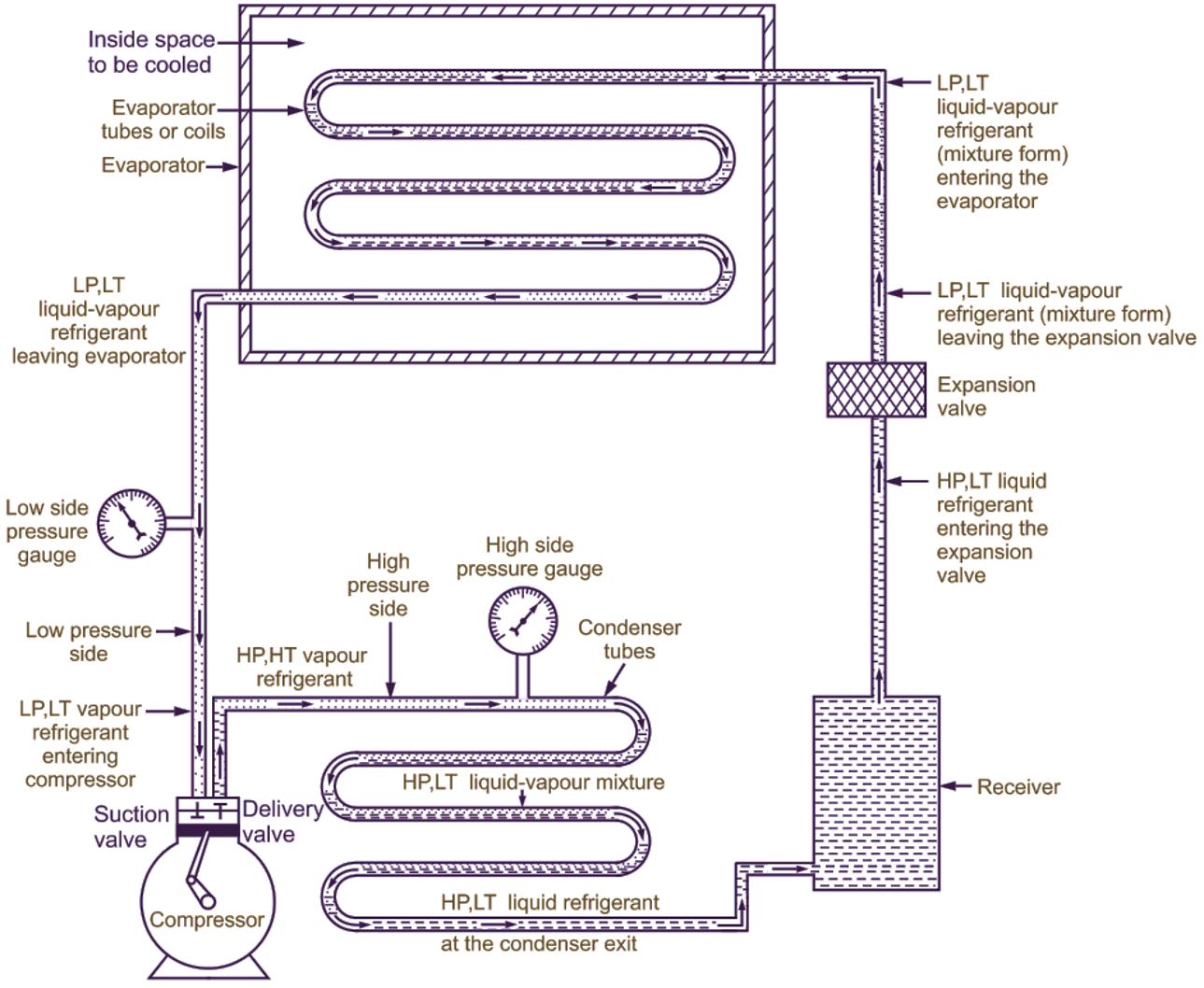
Fig. 1: Vapour compression refrigeration system running on Vapour compression cycle
- Low pressure side – From outlet of expansion valve up to inlet of compressor.
- High pressure side – From outlet of compressor up to inlet of expansion valve.
Compressor
Function of compressor is, “to compress low pressure, low temperature vapour refrigerant to convert it into high pressure, high temperature vapour refrigerant”. The low pressure and low temperature vapour refrigerant from evaporator is drawn into the compressor through inlet or suction valve, where it is compressed to high pressure and high temperature. The high pressure and high temperature vapour refrigerant is discharged into the condenser through delivery or discharge valve.
Condenser
Function of condenser is, “to provide a heat transfer surface, through which, heat passes from the hot vapour refrigerant to the condensing medium like atmospheric air”. The condenser consists of cols or pipes, in which, high pressure and high temperature vapour refrigerant is cooled and condensed. While passing through the condenser coils, the high pressure, high temperature vapour refrigerant gives up its latent heat to the surrounding condensing med um (which is normally air or water) and gets converted to high pressure, ow temperature, liquid refrigerant, which leaves the condenser and enters the expansion device or valve.
Expansion Device or Valve
Function of expansion device or valve is, “to reduce the pressure of liquid refngerant entering the evaporator, so that, liquid refrigerant wi// vapourize at very low temperature in the evaporator by absorbing latent heat from the substance or space to be cooled”. Thus, refrigerant can absorb heat from the substance or space to be cooled in the evaporator at the desired low temperature. Expansion valve also controls the amount of liquid refrigerant entering into the evaporator.
Evaporator
Function of evaporator is, “to provide a heat transfer surface, through which, heat can pass from the refrigerated space to the liquid refrigerant flowing through evaporator coils and thereby vapourizing the liquid refrigerant”. Evaporator consists of wounded coils or pipes, in which, the flowing fluid (i.e. liquid refrigerant at low pressure low and low temperature) absorbs its latent heat of vapourization from the space to be coo ed and gets evaporated to vapour refrigerant. Due to removal of heat (i.e. absorption of heat) by refrigerant, the required space gets cooled producing refrigerating effect. In addition to the above four principal components, other devices such as receiver and strainer – drier assembly may be provided for safety considerations as well as for improving the COP of system.
(a) Receiver
Function of receiver is, “to provide a constant supply of liquid refrigerant to the evaporator as needed”. The condensed liquid refrigerant from the condenser is stored in receiver, from where, it is supplied to evaporator through expansion valve.
(b) Strainer—Drier assembly
Function of strainer is “to remove impurities from the refrigeration system”, The common form of strainer is a fine mesh screen made up of metal, which traps the impurities, contaminants and foreign particles from the system. The strainer can be washed off and refitted or it can be replaced by new one.
Function of drier is “to remove moisture (i.e. water vapour associated with refrigerant) from the refrigeration system”. The common form of drier is a capsule charged with a solid desiccant, which works as a drying agent. The drying agent may be silica gel, activated alumina or zeolite (molecular sieve).
Location of strainer – drier assembly: It is located in the liquid line ahead of the expansion valve.
Block Diagram of Vapour Compression Cycle
Fig. 2 shows the block diagram of vapour compression refrigeration cycle (VCC).
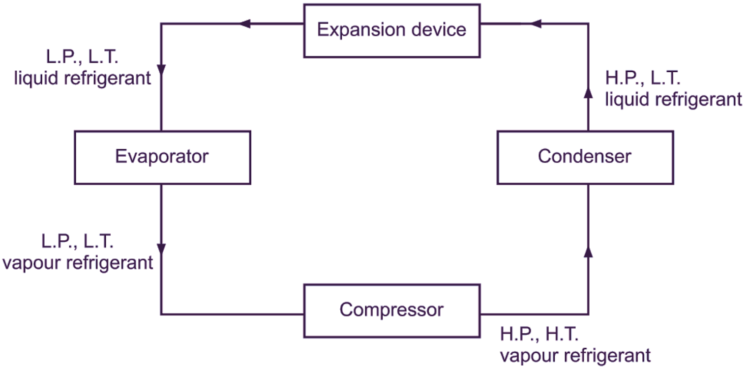
Fig. 2: Block diagram showing vapour compression cycle
Assumptions Made in Theoretical Vapour Compression Cycle
- There are no pressure losses in the condenser, evaporator, compressor, valves and connecting pipelines.
- There is no heat transfer between the system and surrounding except in the evaporator and condenser.
- There are no mechanical or fluid friction losses.
- All processes involved in V.C.C. are reversible.
Advantages of Vapour Compression Refrigeration System over Air Refrigeration System
- The coefficient of performance of vapour compression refrigeration system is quite high, because its working cycle (i.e. vapour compression cycle) resembles closely to the Reversed Carnot cycle.
- Smaller size for given capacity of refrigeration as compared to air refrigeration system.
- The amount of refrigerant circulated in vapour compression refrigeration system is less than air refrigeration system to achieve same refrigeration effect, because the heat removed away by the refrigerant in VCC is the latent heat. As a result of this, size of evaporator is smaller in vapour compression refrigeration system for the same refrigerating effect as compared to air refrigeration system.
- Vapour compression refrigeration system can be employed over a large range of temperatures. By adjusting the expansion valve Of the same unit, the required temperature in the evaporator can be achieved.
- Running cost of VCC is less than air refrigeration cycle (about 1/5th). In other words, refrigeration system requires five times more power than a vapour compression refrigeration system for obtaining the same refrigeration effect.
- Vapour compression refrigeration system is available in various sizes and capacities with easy control,
Disadvantages of Vapour Compression Refrigeration System as compared to Air Refrigeration System
- Leakage of refrigerant in V.C.R. system is the major problem.
- Higher initial investment cost (i.e. capital cost) as compared to air refrigeration system.
- High cost of refrigerant.
- High energy consumption in the form of electricity.
Applications of Vapour compression cycle
- Water cooler
- Cold storage
- Domestic refrigerator
- Air conditioner.
- Ice plant
Comparison of Vapour Compression Cycle and Reversed Carnot Cycle
Vapour Compression Cycle
- Practical cycle giving lesser COP as compared to Reversed Carnot Cycle.
- Includes throttling expansion.
- Constant pressure and constant temperature heat absorption and heat rejection processes.
- Dependent on the type of refrigerant (working substance) used.
- Most popular in refrigeration applications.
Reversed Carnot Cycle
- Ideal cycle giving highest COP.
- Includes isentropic expansion.
- Constant temperature heat absorption and heat rejection processes.
- Only air can be used as refrigerant. Therefore, it is said to be independent of refrigerant (working substance) used.
- It cannot be practcally implemented, due to its own limitations.
Pressure-Enthalpy Chart
P-h chart is essential to study a vapour compression refrigeration cycle. This chart acts as a tool in understanding the behaviour of a refrigerant. Pressure is plotted on Y-axis (i.e. ordinate axis) and enthalpy (i .e. abscissa axis) as shown in Fig. 3.
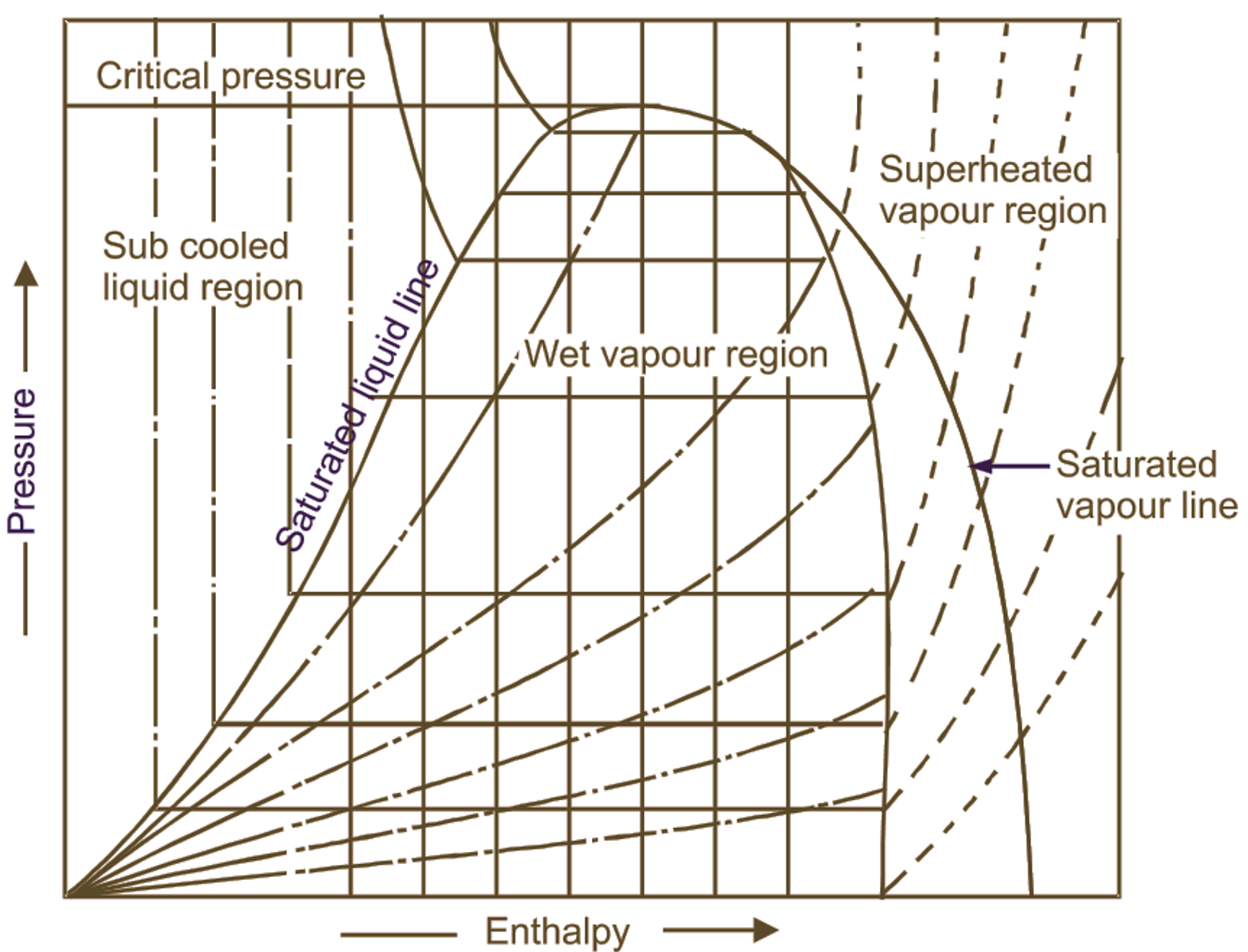
Fig. 3: Pressure enthalpy chart (P – h Chart)
The saturated liquid line and saturated vapour line meet and merge together at a critical point. A saturated liquid is one, which has a temperature equal to its saturation temperature corresponding to its pressure. Space to the left of saturated liquid line (or curve) is known as subcooled liquid region. The region to the right of saturated vapour line (or curve) is known as superheated vapour region. The region between saturated liquid line and saturated vapour line is known as wet vapour (i .e. mixture of vapour refrigerant and liquid refrigerant) region.
Representation of Vapour Compression Cycle on p-h and T-S Charts
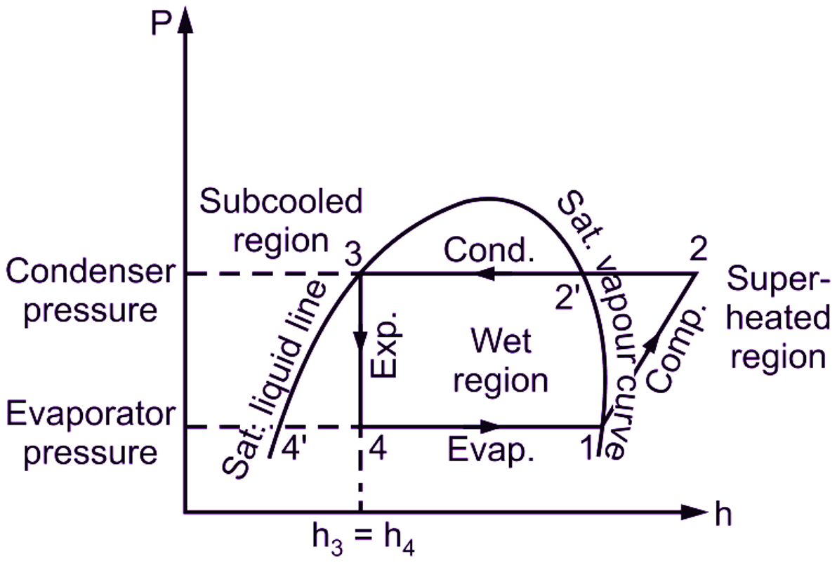
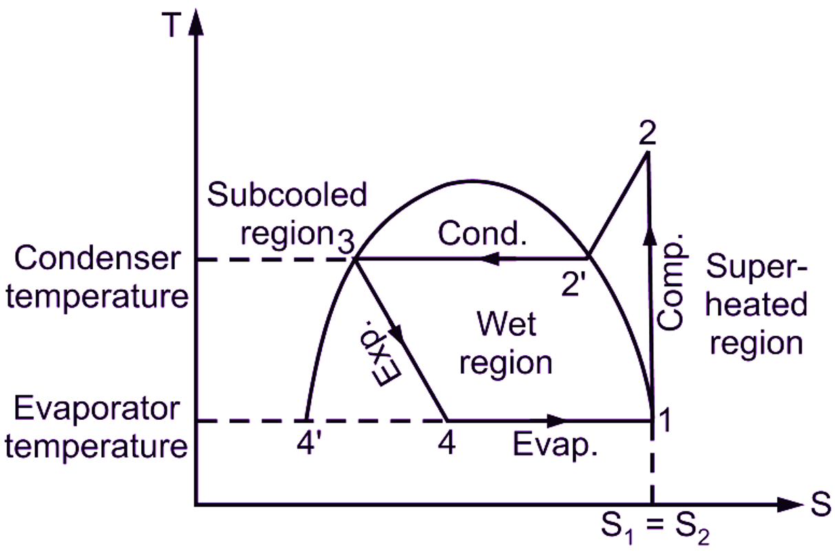
Fig. 4; Representation of vapour compression cycle on P-h and T-S diagrams (Dry compression)
Pressure Sides of Vapour Compression Cycle
In any vapour compression refrigeration system running on vapour compression cycle (V.C.C.). there are two different pressure regions (Figure 5).
High-pressure side: It includes discharge line (i .e. piping from delivery valve to condenser), condenser, receiver and Inlet to expansion valve (i.e. expansion device).
Low-pressure side: It includes evaporator, piping from outlet of expansion valve or expansion device to evaporator and suction line (i.e. piping from evaporator to suction valve).
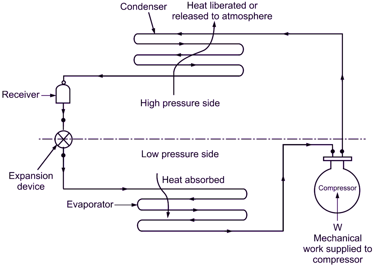
Fig. 5: Pressure sides of vapour compression cycle
Use of Accumulator and Flash Chamber in Vapour Compression Cycle
Accumulator
An accumulator is provided just after the evaporator. It is a large-sized container designed to trap liquid refrigerant (if any) coming out of evaporator due to incomplete evaporation (Figure 6).
Function of accumulator: The accumulator prevents any portion of liquid refrigerant associated with vapour refrigerant from entering the compressor. In other words, it allows only dry vapour refrigerant to pass forward to compressor. Thus, the accumulator saves the compressor from being damaged by any amount of liquid refrigerant and avoids wet compression.
Flash Chamber
Flash chamber is a tank, which is fitted always after the expansion valve (such as, capillary tube or throttling device), but before the evaporator in a vapour compression refrigeration system. In short, flash chamber is located in between expansion device and evaporator. It has been observed that, while passing through capillary tube or any throttling device, some part of the liquid refrigerant always gets evaporated during the expansion process. Thus, the throttling device always supplies a vapour-liquid mixture of refrigerant to the evaporator. The liquid part of mixture absorbs latent heat from the evaporator (space to be cooled) and gets vapourised giving refrigeration effect. Whereas, if the vapour part of refrigerant coming out of the expansion device is supplied to the evaporator, it will not pick up any heat there and wi I just pass out serving no purpose in the evaporator (i.e. without serving any purpose).
Functions of Flash Chamber
The flash chamber separates vapour refrigerant and liquid refrigerant and sends the dry vapour refrigerant direct to compressor bypassing the evaporator. And only the liquid refrigerant goes to the evaporator to produce refrigeration effect. Thus, the mass of refrigerant going to the evaporator is decreased, which reduces the required size of evaporator and provides better conditions for heat transfer. Thermodynamically, use of flash chamber has no effect on the refrigeration cycle.
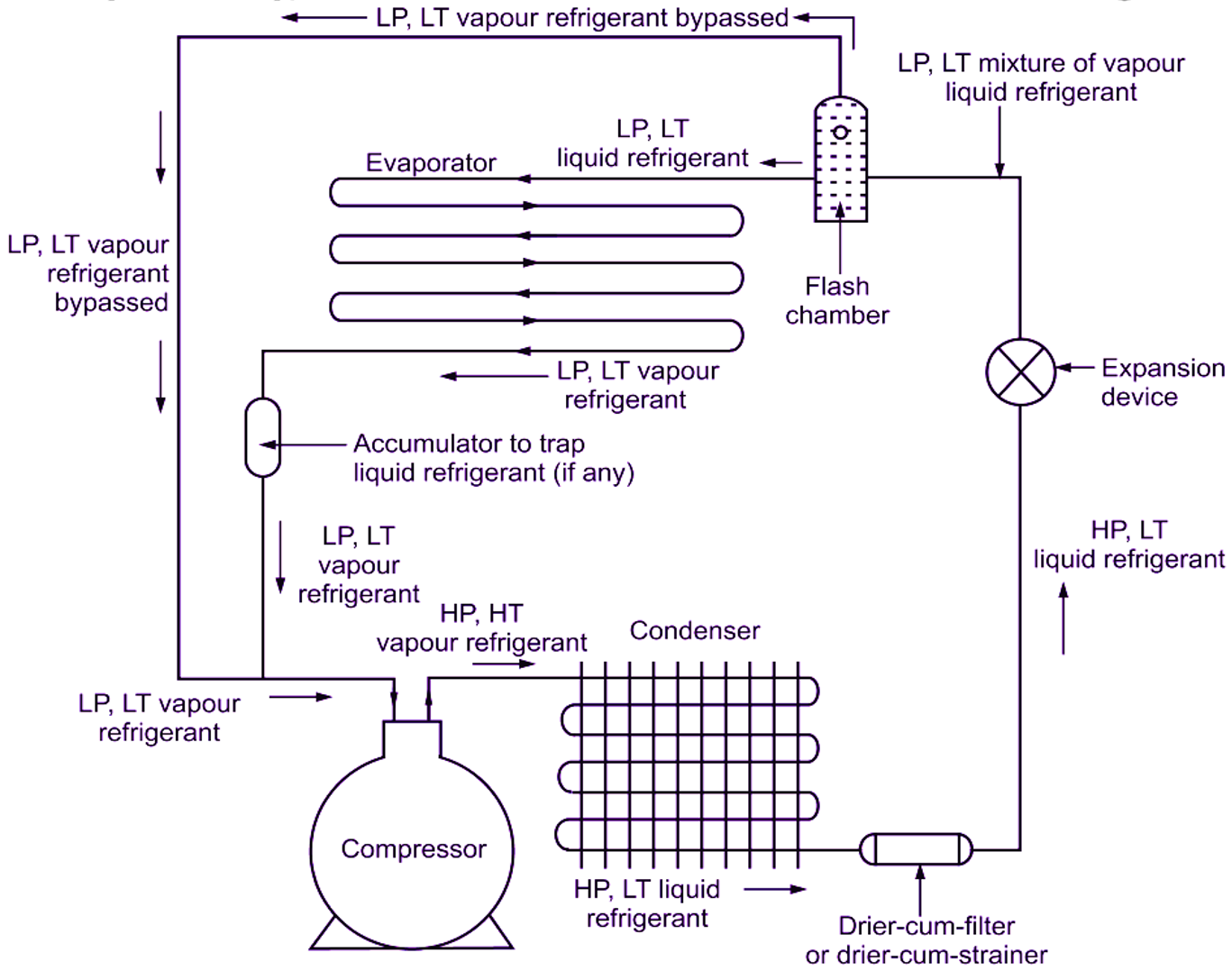
Fig. 6: Use of accumulator and flash chamber
Types of Vapour Compression Cycles
On the basis of state of refrigerant, vapour compression cycle can be represented in several types as
- Dry compression: Cycle with dry saturated vapour refrigerant at inlet of compressor and superheated vapour after compression (i.e. at outlet of compressor).
- Wet compression:
(i) Cycle with wet vapour refrigerant at outlet of compressor and dry saturated vapour at outlet of compressor.
(ii) Cycle with wet vapour refrigerant, both at inlet (before compression) and at outlet (after compression) of compressor.
- Cycle with superheating of vapour refrigerant, before it enters the compressor.
- Cycle With undercooling or subcooling of liquid refrigerant, before it enters the expansion valve.