The transient overvoltages can switch on the thyristor. In some cases, the thyristor can be damaged due to these transient voltages. These transient voltages are very common when the converter is having inductive loads. The thyristors T1 can be protected against transient voltages by a RC network as shown in Fig. l. This RC network is connected in parallel across the thyristor T1. It is called snubber circuit.
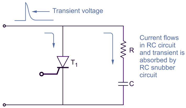
Fig. 1: A snubber (RC) network is used for transient voltage protection.
Every thyristor has maximum permissible value of $di/dt$. The thyristor can di be protected from excessive $di/dt$ by using an inductor in series as shown in Fig. 2. The inductance opposes for rapid current variations $di/dt$. Whenever there is rapid current variation, the inductor smooths it and protects the thyristor from damage.
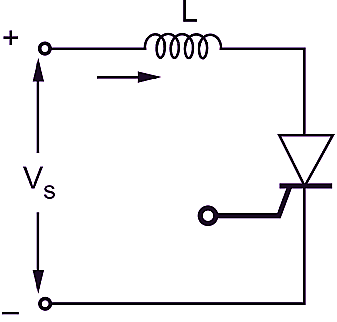
Fig. 2: An inductance in series with the thyristor provides protection against $di/dt$.
Following equations are used to calculate the values of snubber components.
\[C={{\left( \frac{0.564{{V}_{m}}}{dv/dt} \right)}^{2}}\]
\[R=2\sigma \sqrt{\frac{L}{C}}\]
\[L\ge \frac{{{V}_{S}}}{di/dt}\]