In this topic, you study Diode Rectifier – Circuit Diagram, Working & Theory.
Diode rectifiers use only diodes for conversion of input ac voltage to output dc voltage, and the output dc voltage cannot be controlled. Hence, it is also known as an Uncontrolled rectifier.
Diode Rectifier with Resistance Inductive (RL) type of load
In most of industrial applications, load is inductive, for example, single phase ac motor. The windings of the motor are inductive and the resistance of the winding coils make it a RL (Resistance-Inductive) type of load. Fig. 1 shows a single-phase half-wave rectifier with RL load and its waveforms.
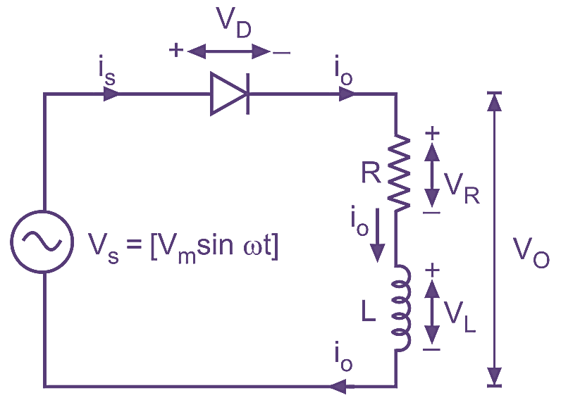
(a) Circuit diagram.
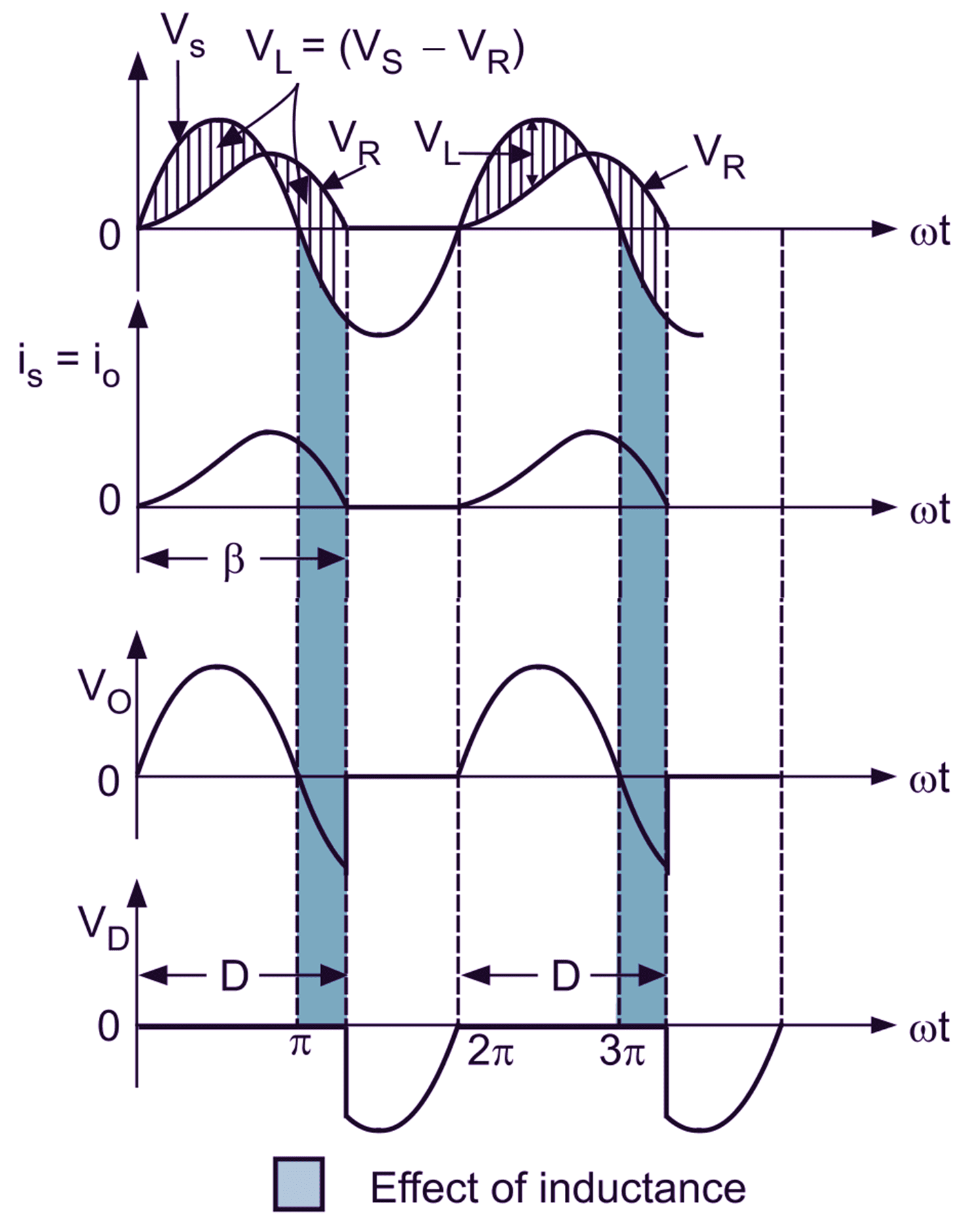
(b) Waveforms.
Fig. 1: Single-phase half-wave diode rectifier with RL load.
It can be seen that load current io flows even after source voltage has become negative. This is the effect of load inductance. After π, even if source voltage goes negative, the back emf stored in the inductor maintains the direction of load current io for some time. At β, all the energy in the inductor is pushed in the load and the load current io becomes zero. This is shown in Fig. 1 (b) as gray area. Also note that, the load current (io) waveform and output voltage (Vo) waveform are not exactly identical. This is because the inductor opposes any change in current and hence io slowly builds up and decays. To find the average output voltage, we integrate input voltage over the period from 0 to β.