In this topic, you study Square Wave Inverter – Definition, Circuit Diagram & Waveform.
Square Wave Inverter is an electrical circuit, converts a fixed voltage DC to a fixed (or variable) square wave AC voltage with variable frequency.
Circuit Diagram & Working of the Square Wave Inverter
The full-bridge configuration of a Square Wave Inverter is shown in Fig. 1 (a). Thyristors Th1 and Th2 are fired during the first half-cycle and thyristors Th3 and Th4 are fired during the second half-cycle of the output voltage. The output voltage is a square wave of amplitude V as shown in Fig. 1 (b). The frequency of the firing pulses decides the frequency of the inverter.
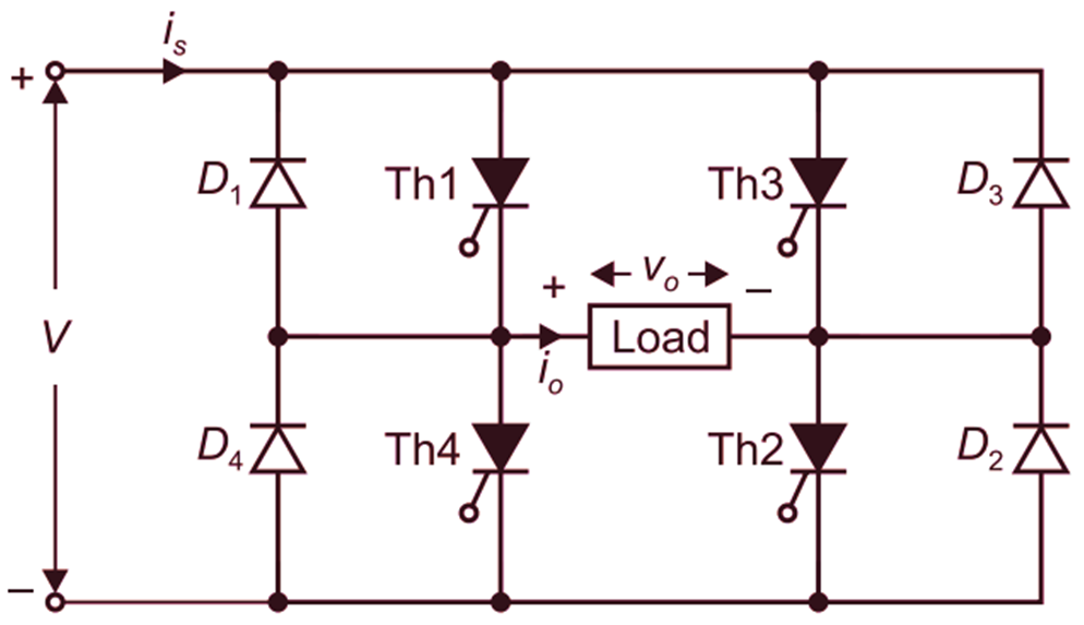
(a)
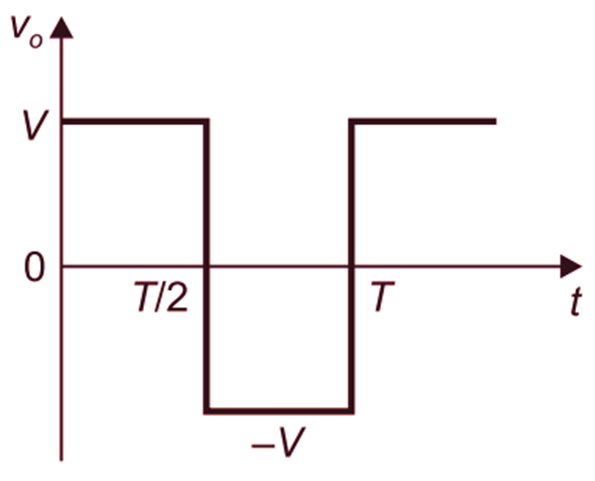
(b)
Fig. 1: The full-bridge configuration of a single-phase voltage source inverter