In this topic, you study DC Circuit Breaker – Diagram & Working.
Figure 1 shows a simple type of static dc circuit breaker in which the thyristors are used for making and breaking the dc circuits. Here thyristor Th1 is called the main thyristor and Th2 is the auxiliary thyristor. Thyristor Th2 has the function to turn off Th1 when required. In case of dc there is no natural zero to turn off Therefore capacitor is used. Here, capacitor C provides the required commutation of the main thyristor, since the current does not have a natural zero value in a dc circuit. When thyristor Th1 is conducting, the load voltage will be equal to the supply voltage and capacitor C will get charged through resistance R1. The breaking of the circuit is achieved by turning off thyristor Th1. This is done by firing thyristor Th2. Then capacitor C will discharge through thyristors Th2 and Th1. This current will oppose the load current flowing through thyristor Th1 and when these two currents become equal, the net current will be zero and thyristor Th1 will be turned off thereafter, capacitor will get charged through the load and during this time a reverse potential across thyristor Thi will be applied. When capacitor C is fully charged, thyristor Th2 will be turned off because the current through the load is Fig. 1 DC circuit breaker zero and the current through resistance R1 is below the value of holding current of thyristor Th2.
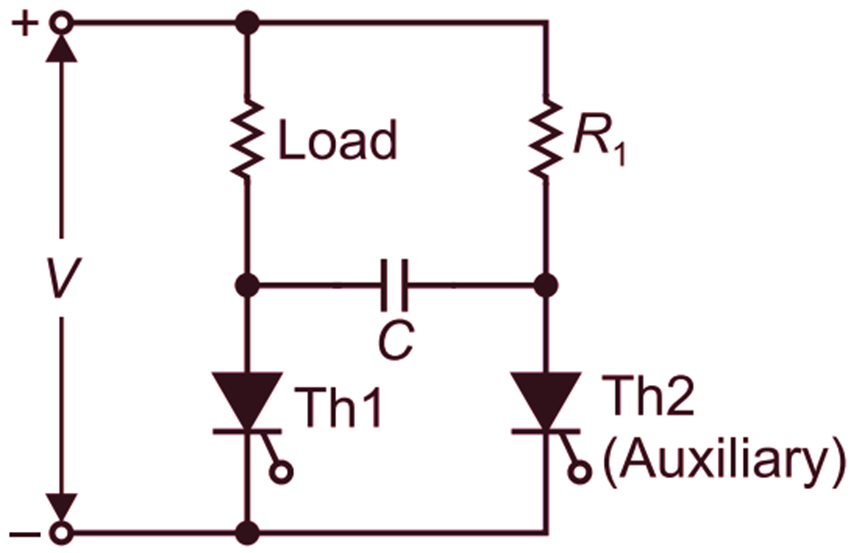
Fig.1: DC Circuit Breaker