In this topic, you study Sine Wave Inverter – Definition, Circuit Diagram, Waveforms & Advantages.
Sine Wave Inverter uses Sinusoidal Pulse Width Modulation (SPWM) technique to control the output voltage of the inverter. Sinusoidal pulse width modulation is basically a multiple pulse width modulation which provides number of pulses of unequal width in each-cycle of the output voltage. Here, the width of the pulse is a function of sine wave instead of being constant, as in multiple pulse width modulation. With this modulation, the harmonics in the output voltage can be reduced and hence a smooth voltage control can be obtained.
Circuit Diagram of the Sine Wave inverter
The construction of the sine wave inverter is shown in Fig. 1.
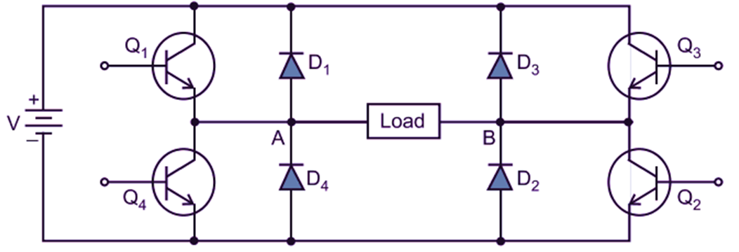
Fig. 1: Sine Wave inverter
Sine Wave Inverter Control technique
The reference signal is a sine wave. While the carrier waveforms is triangular in nature shown in Figure 2. The signals used for triggering the switching devices (transistor) are generated by comparing a reference signal (sine-wave) with a triangular wave as shown in Figure 3.
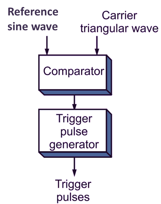
Fig. 2: Sine Wave Inverter Control technique Block Diagram
The triggering pulses are obtained at the point of intersection of the carrier and a reference signal (sine wave). The switching devices are ON until the magnitude of sine wave is greater than that of triangular wave. i.e. Vr > Vc else it is turned OFF. The comparison operation is carried out in a comparator when Vr > Vc the comparator output is maintained high else it is low. By controlling the modulation index M, (i.e. ratio of Vr / Vc), the harmonic content in the output voltage can be controlled.
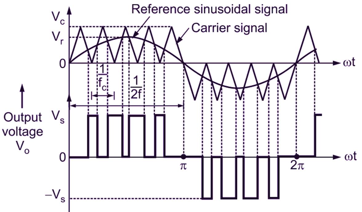
Fig. 3: Sinusoidal-pulse-width modulation