A voltage to current converter is a voltage-controlled current source. An ideal voltage controlled current source has two characteristics.
1. It produces current io proportional to the controlling voltage Vi,
i.e.,
\[{{i}_{o}}\propto {{V}_{i}}\]
\[{{i}_{o}}=k{{V}_{i}}\]
where k is in ohms
2. The produced current, io is independent of the load resistance, RL
There are two versions of the voltage-to-current converter. They are,
- Voltage to current convener with floating load
- Voltage to current converter with grounded load.
Voltage to current converter with Floating load:
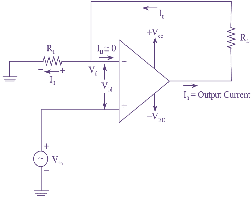
Figure (1): V to I Converter with Floating Load.
Figure (1) represents a voltage to current converter with floating load resistor RL i.e, it is not connected to ground. The input voltage is applied to the non-inverting input terminal and the feedback voltage across R1 drives the inverting amplifier. As the feedback voltage across R1 is dependent upon the output current i0 and is in series with difference input voltage Vid, the circuit in figure (1) is also known as current-series negative feedback amplifier.
Applying KVL for the input loop, we get,
\[{{V}_{in}}={{V}_{id}}+{{V}_{f}}\]
But Vid ≅ 0V, Since gain A is very large
\[{{\text{V}}_{\text{in}}}=\text{0}+{{\text{V}}_{\text{f}}}\]
\[{{\text{V}}_{\text{in}}}={{\text{V}}_{\text{f}}}\]
\[{{\text{V}}_{\text{in}}}={{\text{R}}_{\text{1}}}{{\text{i}}_{\text{o}}}\]
\[\text{ }{{\text{i}}_{\text{o}}}\text{=}\frac{{{\text{V}}_{\text{in}}}}{{{R}_{1}}}\]
Thus the input voltage Vin appears across R1 The output current ‘io’ is precisely fixed if ‘R1’ is a precision resistor.
Voltage to Current Converter with Grounded Load:

Figure (2): V to I Converter with Grounded Load.
Figure (2) represents the voltage-to-current converter with the load being grounded. In figure (2), the load current is controlled by an input voltage and one terminal of the load is grounded.
Applying KCL at node V1 we get,
\[{{I}_{1}}+{{I}_{2}}={{I}_{L}}\]
\[\frac{{{V}_{in}}-{{V}_{1}}+{{V}_{o}}-{{V}_{1}}}{R}={{I}_{L}}\]
\[{{V}_{in}}+{{V}_{o}}-2{{V}_{1}}={{I}_{L}}.R\]
\[2{{V}_{1}}={{V}_{in}}-{{V}_{o}}-{{I}_{L}}.R\]
\[{{V}_{1}}=\frac{{{V}_{in}}-{{V}_{o}}-{{I}_{L}}.R}{2}\]
As the operational amplifier is connected in the non inverting mode, the gain of the circuit is given by.
\[\frac{{{V}_{o}}}{{{V}_{1}}}=1+\frac{R}{R}=2\]
\[{{V}_{o}}=2{{V}_{1}}\]
Substituting the value of V1 in equation (1), we get,
\[{{V}_{o}}=2\left[ \frac{{{V}_{in}}+{{V}_{o}}-{{I}_{L}}.R}{2} \right]\]
\[{{V}_{o}}={{V}_{in}}+{{V}_{o}}-{{I}_{L}}.R\]
\[{{V}_{in}}={{I}_{L}}.R\]
\[{{I}_{L}}=\frac{{{V}_{in}}}{R}\]
Therefore, the load current is dependent upon the input voltage ‘Vin’ and the resistor ‘R’. Precautions had to be taken while the selection of measures load and feedback resistors Rf and RL due to the below reasons.
(i) When Rf and RL are of very low values, the op-amp might be driven into saturation, since the op-amp produces large output Current.
(ii) When Rf and RL are of very high values, then the circuit may explode. since output voltage reaches beyond the power supply.