For the large power, variable speed drives, the 3 Phase AC to DC converters are extensively used. The average output voltage of 3 phase converter provides higher and hence its D.C. output is suitable for large power DC loads.
Types of 3 Phase Converter
Three-phase converters are mainly classified into three classes like single-phase converters (rectifiers).
- Half-wave converters.
- Full-wave converters.
- Dual converter.
Full-wave converters are further classified into two classes:
- Fully-controlled converters.
- Half-controlled converters.
Three-Phase Half-Wave Controlled Converter (With Highly Inductive Load)
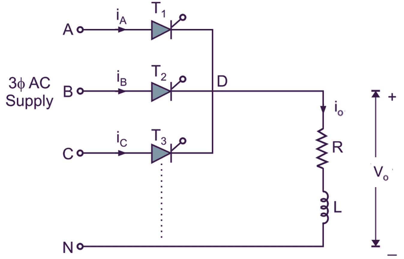
Fig. 1: Circuit diagram of three-phase half-wave controlled converter with highly inductive load.
Fig. 1 shows the circuit diagram of three-phase half wave controlled converter with highly inductive load. This circuit provides the load current i0 is ripple free and continuous. The conduction period for each SCR is 2π/3 radians or 120°. Three phases VAN, VBN and VCN are applied for SCRs T1, T2 and T3 respectively. The load is connected between common cathode point of the three SCRs i.e. point D and neutral point N.
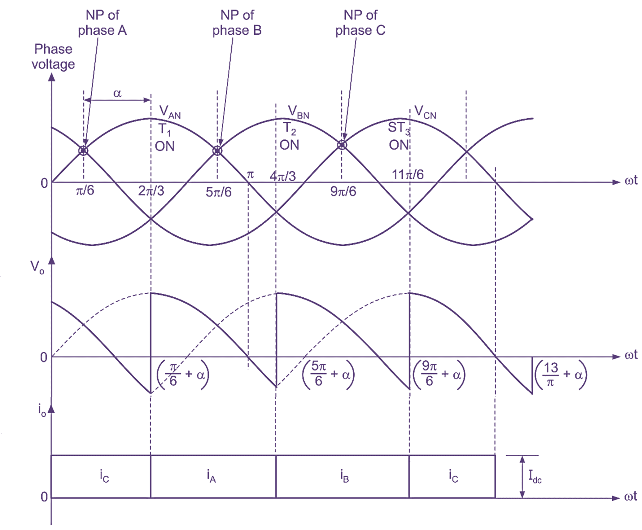
Fig. 2: Input, output voltage and current waveforms of three-phase half-wave controlled converter with RL load.
The average output voltage is controlled with the help of firing angle (α), from positive maximum to zero. Unlike the reference point of α, being the zero-crossover instant for single-phase system, here the reference or neutral point NP is the crossover point of voltage value of two phases as shown in Fig. 2. Therefore, the NP (neutral point) for phase A, B and C are ωt = π /6, 5 π /6 and 9 π /6 respectively. Since there are three voltage pulses, NP for each phase is displaced by 120°.
3 Phase Converter Operation:
The operation of three-phase half-wave controlled converter with RL load consists of three modes:
Mode 1:
At instant ωt = (π/6 + α) or 30° + α, the SCR T1 triggered, the phase voltage VAN reaches to the load. The thyristor acts as a mechanical switch and V0 is same as VAN. As the SCR T1 is turned ON, the conducting thyristor T2 is turned OFF due to line commutation.
In this mode of operation, the load voltage V0 and load current I0 both positive, so the inductive load will store energy. After some time at ωt = π, the supply voltage VAN goes through zero, and after π it becomes negative. The conducting thyristor T1 try to turn-off due to reverse voltage appeared across the thyristor T1. But due to stored energy in inductive load, the thyristor T1 continues to conduct in negative half cycle for some period.
Mode 2:
At instant ωt = (5π /6 + α) or (150° + α), SCR T2 is triggered, the load current immediately transferred from T1 to T2. The load voltage is equal to phase voltage VBN i.e. V0 = VBN. Since the conduction of thyristor T2 continues upto 9π /6 + α, even negative voltage reaches to load (as commutation does not take place at ωt = π due to stored energy in inductive load).
SCR T2 commutate at ωt = 9π /6 + α
Mode 3:
At instant ωt = (9π /6 + α) or (330° + α), the SCR T3 is triggered, the line voltage VCN appears across the load. This mode of operation is very similar to previous two modes.
Formulas of 3 Phase Converter
Average value of output voltage
\[{{\text{V}}_{\text{o}}}=\frac{\text{3}\sqrt{3}{{\text{V}}_{\text{m}}}}{\text{2 }\text{ }\!\!\pi\!\!\text{ }\text{ }}\cos \alpha \]
RMS value of output voltage
\[{{\text{V}}_{\text{rms}}}=\sqrt{3}{{\text{V}}_{\text{m}}}{{\left( \frac{\text{1}}{\text{ }6\text{ }}\text{ }+\text{ }\frac{\sqrt{3}}{\text{ 8}\text{ }\text{ }\!\!\pi\!\!\text{ }\text{ }}\text{cos 2 }\alpha \right)}^{\text{1/2}}}\]
Difference between 3 Phase Converter and 1 Phase Converter
| Single-Phase Converters | Three-Phase Converters |
| These are mainly used for low power D.C. loads. | Three-phase A.C. to D.C. converters are preferred for high power D.C. load. |
| Filtering requirement for smoothing out load current is more. | Due to presence of large ripple frequency, filtering requirement for smoothing out the load current is reduced. |
| D.C. motor performance is not better if fed from single-phase converter. | As the load current is continuous, D.C. motor performance is superior as compared to single-phase converter fed. |
| Non-uniform loading occurs if used for high power D.C. drives. | Uniform loading occurs if used for high power D.C. drives. |
| Less number of thyristors are required. | More number of thyristors are required. |
| Suitable for low current rating applications. | Suitable for high current applications. |
| Mid-point converter requires two SCRs and bridge converter requires four SCR: | Mid-point converter requires six SCRs and bridge converter also requires six SCRs. |
| Single-phase converter is less expensive. | Three-phase converter is more expensive. |
| It requires simple triggering circuit. | It requires complex triggering circuit. |
| Construction of circuit and mounting is easy | Construction of circuit and mounting is complex |