If two full converters are connected back to back as shown in Fig. 1 both the output voltage and load current flow can be reversed. The system will provide four quadrant operation and is called as dual converter. Dual converters are normally used in high power variable speed drives. If α1 and α2 are the delay angles of converters 1 and 2 respectively, the corresponding average output voltages are Vo1 and Vo2.
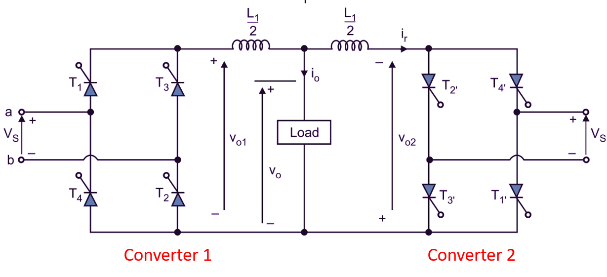
(a) Circuit diagram
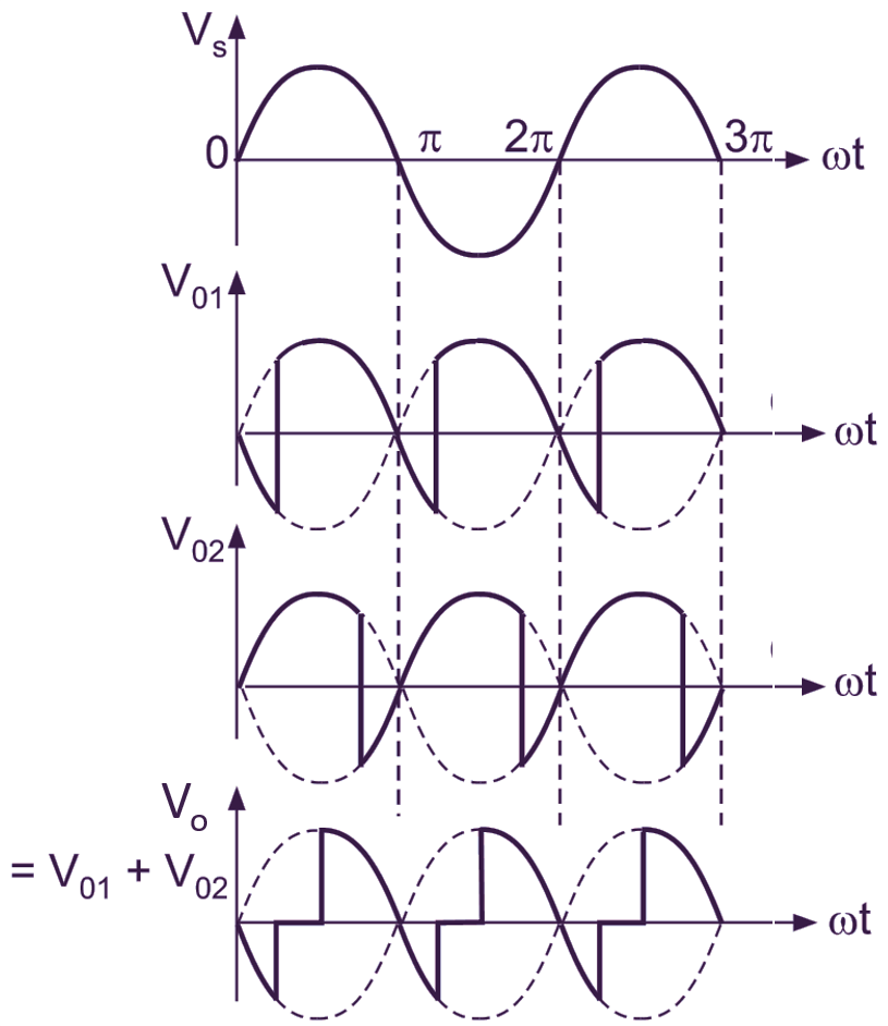
(b) Input and output voltage waveforms of Converter 1 and converter 2
Fig. 1: Single-phase dual Converter
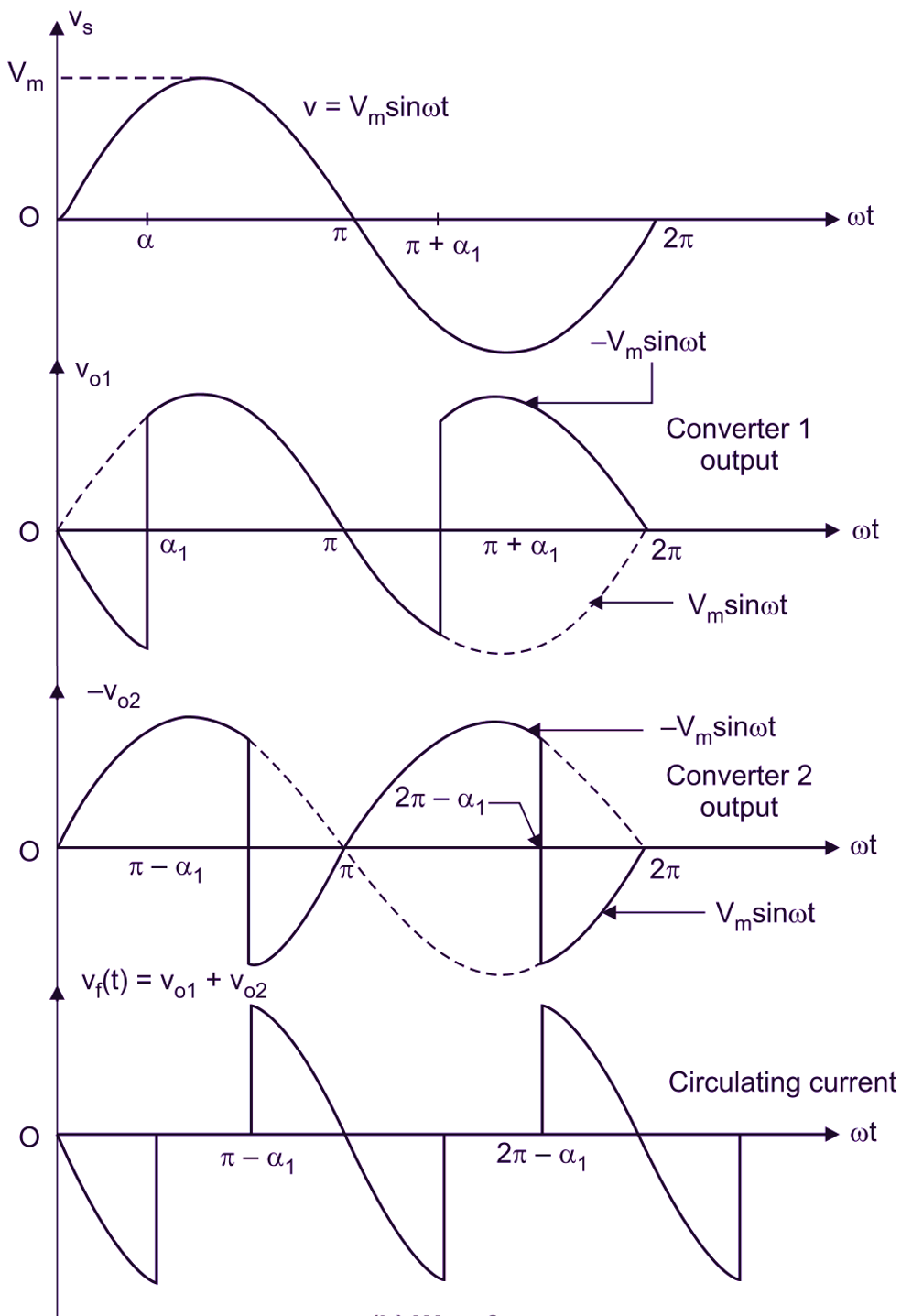
The delay angles of converters are controlled in such a way that one converter operates as a rectifier and other converter operates as an inverter, but both converters produce the same average output voltage. Fig. 1 (b) shows the output waveforms for two converters, where the two average Output voltages are the same. The average output voltage of converter 1 is,
\[{{\text{V}}_{\text{o1}}}=\frac{\text{2}{{\text{V}}_{\text{m}}}}{\text{ }\!\!\pi\!\!\text{ }}\cos {{\alpha }_{1}}\]
and for converter 2, output voltage is,
\[{{\text{V}}_{\text{o2}}}=\frac{\text{2}{{\text{V}}_{\text{m}}}}{\text{ }\!\!\pi\!\!\text{ }}\cos {{\alpha }_{2}}\]
Since one converter is rectifying and Other one is inverting,
If α1 and α2 are the delay angles of converters 1 and 2 respectively, the corresponding average output voltages are .
Vo1 = – Vo2
or
cos α1 = – cos α2
α2 = π – α1
Since the instantaneous output voltages of two converters are out of phase, there will be an instantaneous voltage difference and this will result In circulating current between two converters. This circulating current will not flow through the load and is normally limited by circulating current reactor L1 as shown in Fig. 1.
The dual converters can be operated with or without circulating current, only one converter operates at a time. When circulating current is not present however, Other converter is completely blocked by inhibiting gate pulses.
Single Phase Dual Converter with Inductive Load
The back to back connection of two fully controlled converters across the load circuit is named as Dual converter. The single phase full converters allow only two quadrant operation with inductive loads to extent the operation to four quadrant the dual converters are used (Fig. 2).
(a) Circuit diagram
(b) Input and output voltage waveforms of Converter 1 and converter 2
Fig. 2: Single Phase Dual Converter with inductive load