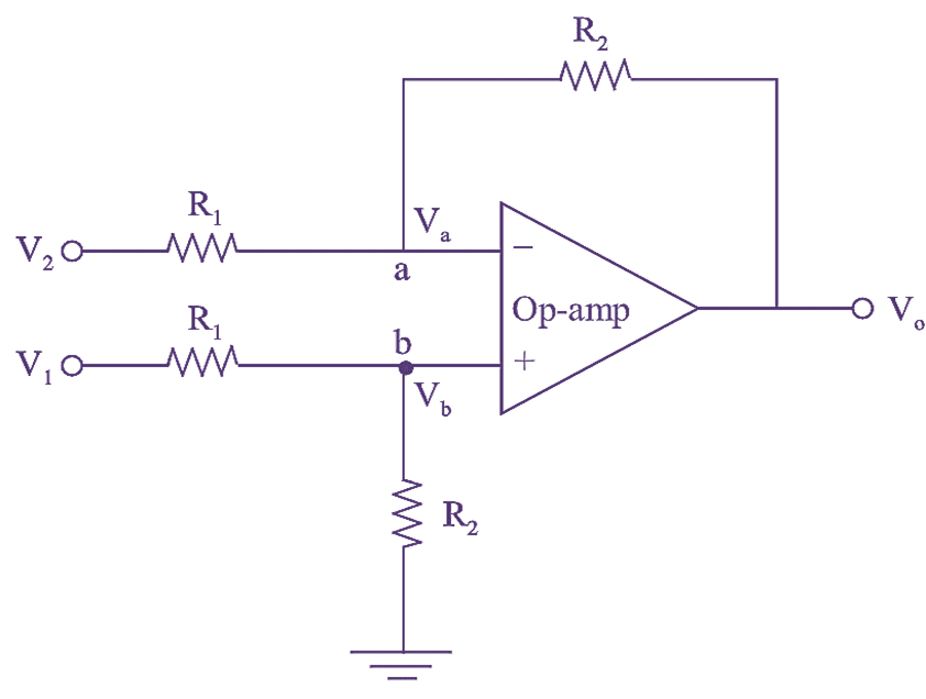
Figure (1): Differential Amplifier.
Differential (or Difference) amplifier or a subtractor is defined as a circuit, which amplifies the difference between two input signals. It effectively amplifies the difference between signals applied at its inverting and non-inverting terminals. Hence, it is also referred as differential or difference amplifier. The schematic arrangement of op-amp based Difference amplifier is as shown in figure (1).
The voltage drop at node a and b are same provided that the difference in input terminal is zero.
By applying KCL at node a, we get
\[\frac{{{V}_{a}}-{{V}_{2}}}{{{R}_{1}}}+\frac{{{V}_{a}}-{{V}_{0}}}{{{R}_{2}}}=0\]
\[{{V}_{a}}\left[ \frac{1}{{{R}_{{}}}}+\frac{1}{{{R}_{F}}} \right]-\frac{{{V}_{2}}}{{{R}_{1}}}=\frac{{{V}_{0}}}{{{R}_{2}}} ….(1)\]
By applying KCL at node b, we get
\[\frac{{{V}_{b}}-{{V}_{1}}}{{{R}_{1}}}+\frac{{{V}_{b}}}{{{R}_{2}}}=0\]
\[{{V}_{b}}\left[ \frac{1}{{{R}_{1}}}+\frac{1}{{{R}_{2}}} \right]-\frac{{{V}_{1}}}{{{R}_{1}}}=0 ….(2)\]
By subtracting equation (2) from equation (1), we get
\[\frac{1}{{{R}_{1}}}\left( {{V}_{1}}-{{V}_{2}} \right)=\frac{{{V}_{0}}}{{{R}_{2}}}\]
\[{{V}_{0}}=\frac{{{R}_{2}}}{{{R}_{1}}}\left( {{V}_{1}}-{{V}_{2}} \right)\]
Where the Gain (A) of the op-amp is
\[{A}=\frac{{{R}_{2}}}{{{R}_{1}}}\]
The output voltage of an op-amp based differential amplifier is.
\[{{V}_{0}}=\frac{{{R}_{2}}}{{{R}_{1}}}\left( {{V}_{1}}-{{V}_{2}} \right)\]..
Assuming equal values of resistances i.e., R1 = R2, then
\[{{V}_{0}}={{V}_{1}}-{{V}_{2}}\]