In this topic, you study Freewheeling Diode – Definition, Diagram, Working & Advantages.
A freewheeling diode is used to make load current continuous and stops the output voltage from going negative. A freewheeling diode is commonly known as commutating diode (or flywheel diode or bypass diode).
Effect of Freewheeling Diode
The freewheeling diode commutates or transfers load current away from the rectifier whenever the load voltage goes into a reverse state.
Half-wave Controlled Rectifier with a Freewheeling Diode
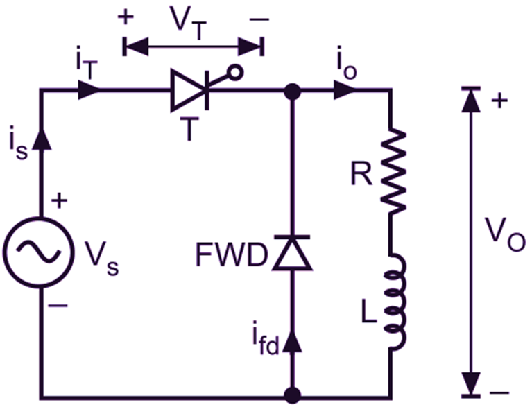
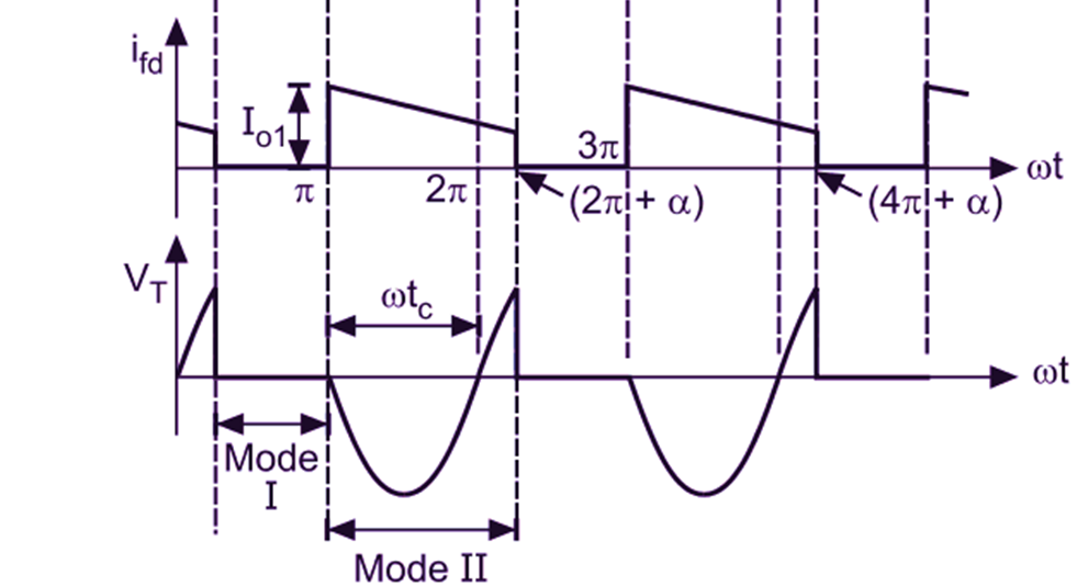
Fig. 1 shows the circuit diagram and its waveforms for a half-wave controlled rectifier with a freewheeling diode FWD connected across R-L load. The working of the circuit can be explained by two modes of operation :
Mode 1: During this mode, SCR is fired at angle α, and it conducts upto ωt = π. Source voltage Vs appears across the load. SCR (T) conducts for α ≤ ωt ≤ π. This mode is called as conduction mode.
Mode 2: After ωt = π, as source voltage Vs tends to reverse, freewheeling diode is forward biased through conducting SCR (T) which is still ON because the load current io is still positive and greater than holding current. As a result, load current io is transferred from SCR to FWD. It is assumed that during freewheeling period when energy stored in the inductor is circulated through load, load current does not decay to zero until the SCR is triggered again. Therefore, the load current remains continuous. This period is called as freewheeling mode.
(a)
(b)
Fig.1: Single-phase half-wave circuit with RL load and a freewheeling diode (a) Circuit diagram, (b) Voltage and current waveforms
Description of Freewheeling Diode Working
Fig. 1 (a) shows a half-wave controlled rectifier with a freewheeling diode FWD connected across R-L load. The load voltage and current waveforms are also shown in Fig. 1 (b). We can see that the FWD will not be able to conduct beyond 180°. During the positive half cycle, voltage is induced in the inductance. The induced voltage will change its polarity as the di/dt changes its polarity and FWD will start conducting as soon as the induced voltage is of sufficient magnitude, which in turn enables the inductance to discharge its stored energy into the resistance.
During the negative half cycle, the load current flows through the diode and a reverse voltage appears across the thyristor T. If the freewheeling diode (FWD) is not present, the energy stored in inductance L is returned to the supply by the thyristor T, during negative half cycle. With the freewheeling diode, no power will be returned to the source. Effectively the freewheeling diode improves the input power factor.
Advantages of Freewheeling Diode
- It does not allow the output voltage to become negative.
- The rectifier efficiency improves because the energy stored in inductor L is transferred to load and is utilized.
- The load performance enhances because the load current is continuous.