An instrument which provides different types of waveforms whose frequency values can be varied and adjusted over a wide range (from a hertz to several hundred kilohertz) is referred as function generator.
A function generator commonly produces sine wave, square wave, triangular wave and sawtooth wave. A pictorial view of function generator shown in Figure 1.
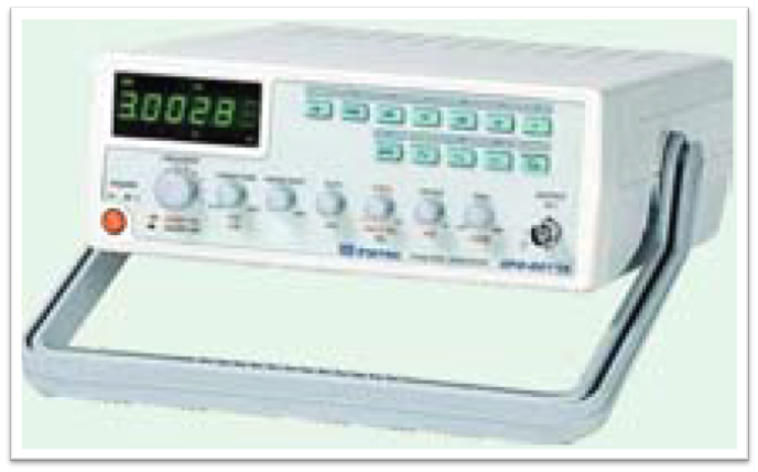
Figure 1: Function Generator.
Block Diagram of a Function Generator
The block diagram representation of a function generator is shown below.
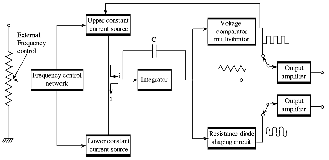
Figure 2: Function Generator Block Diagram.
The frequency control network is governed by the voltage applied externally or the frequency dial provided on the front panel of the device. The output of frequency control network (or frequency controlled voltage) regulates the two current sources i.e., upper constant current source and lower constant current source. The upper constant current source provides current of constant magnitude to the integrator circuit. Therefore the output voltage of integrator linearly increases with respect to time and its output voltage is given by the following equation,
\[{{e}_{out}}=\text{ -}\frac{1}{C}\int\limits_{o}^{t}{idt}\]
When the output current of the upper current source increases, the slope of the integrator output voltage decreases and vice versa. As the positive slope of the output voltage of the integrator reaches a predetermined level, the voltage comparator multivibrator changes its state. This causes the output of upper current supply to the integrator to cut-off and switches on the lower current source supply to the integrator. Now, the lower current source provides a reverse current of constant magnitude to the integrator. Therefore, the output voltage of integrator linearly decreases with respect to time. As the negative slope of the output voltage of the integrator reaches a predetermined level, the voltage comparator multivibrator switches back to its previous state which causes the output of lower current supply to the integrator to cut-off and switches on the upper current source supply.
Therefore, the voltage waveform appears at the output of integrator is triangular and its frequency can be known by the magnitude of current produced by the two current sources. The output of voltage comparator multivibrator is square wave whose frequency is same as that of the triangular wave. The output of integrator which is triangular wave is given to the resistance diode shaping circuit. This circuit alters the slope of the triangular wave into amplitude changes arid provides sine wave of <1% distortion at the output.
The output section of this instrument contains two output amplifiers. These amplifiers provide two selected waveforms among the three individually and simultaneously.
Applications of Function generators
The applications of function generator are as follows,
- Function generator is used to test the bandwidth of the audio frequency amplifier. This process is known as “square wave testing”.
- Function generator acts as source in the alignment of receivers.
- Function generator plays an important role in the trouble shooting different analog and digital circuits.
Specifications of a Function Generator
| Parameter | Specifications |
| Output waveform | (i) Sine wave |
| (ii) Square wave | |
| (iii) Triangular wave | |
| (iv) Ramp up | |
| (v) Ramp down | |
| Frequency range | |
| (i) Sine wave | 10-3 MHz |
| (ii) Square wave | 10-3 MHz |
| (iii) Triangular wave | 10-3 MHz |
| (iv) Ramp signal | 10-3 MHz |
| Resolution | 10-3 MHz |
| Accuracy | Less than 50 PPM |