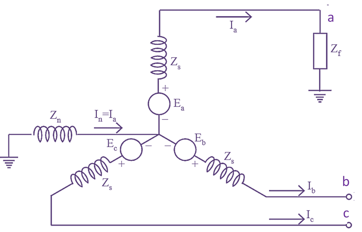
Figure 1: Single Line to Ground Fault. Continue reading What is Single Line to Ground Fault (or LG Fault) in Power System?

Figure 1: Single Line to Ground Fault. Continue reading What is Single Line to Ground Fault (or LG Fault) in Power System?
An equation relating the relative motion of the rotor axis with respect to stator field in time domain is known as swing equation.
or
The equation which describes the behavior of a synchronous machine during transient period is known as swing equation. Continue reading What is Swing Equation? Derivation, Diagram & Formula
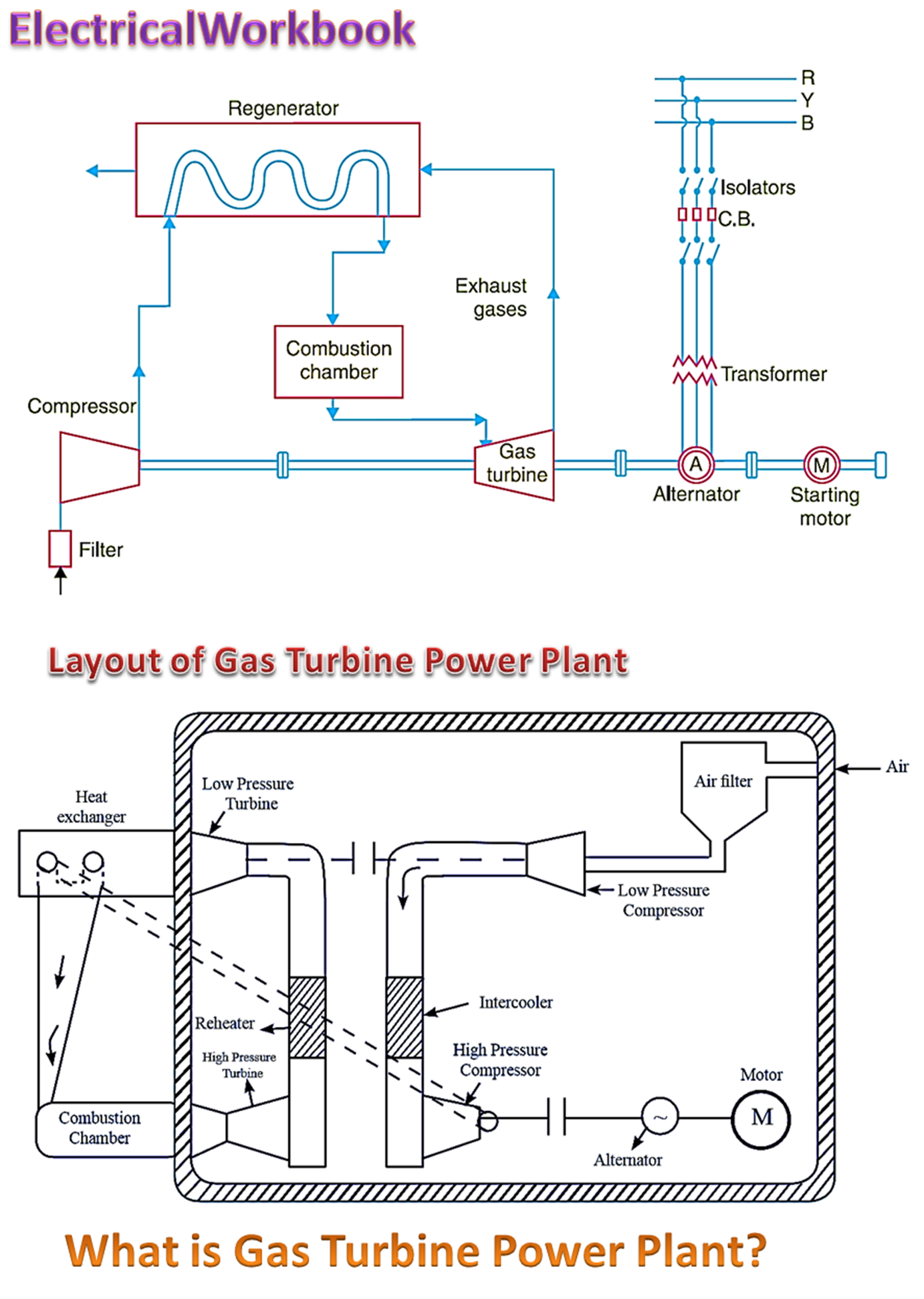
In the gas turbine power plant, electrical energy generation takes place by using gas turbine as the prime mover. Continue reading What is Gas Turbine Power Plant? Working, Diagram & Applications
The electrical load may be defined as the consumption of active and reactive power by an electrical appliance to utilize it for giving the required output from the appliance. It may also be the active and reactive power consumed by all the electrical appliances connected to particular premises such that the electrical appliances produce the desired output. They may be single-phase or three-phase, domestic and commercial types. Continue reading What is an Electrical Load? Explanation, Types & Importance
Interchanging the positions of conductors at regular intervals along the line so that each conductor occupies another conductor's position at an equal distance is known as Transposition of Transmission Line.
When in case of an overhead transmission line, all the three phases are supposed to be spaced symmetrically keeping the line constants, identical but due to some mechanical considerations it in not so, these are placed irregularly. It disturbs the line constants, as a result the voltage drop in the three lines will be different and unequal line voltage is achieved at the receiving end. Continue reading Transposition of Conductors | Transposition of Transmission Line
The relay which operates based on the frequency and produces a tripping signal when the magnitude of frequency drops below a predetermined value is known as under frequency relay. Under frequency relays are either electromagnetic type or static type. Continue reading What is an Under Frequency Relay? Working, Diagram & Construction
The transformer is heart of power system. Power transformer is a major equipment in power system. It requires highly reliable protective devices. The protective scheme depends on size of transformer. The rating of transformers used in transmission and distribution systems range from few kVA to several hundred MVA. For small transformers, simple fuse is sufficient for protection. For medium capacity transformers over current relays are used. For large transformers differential protection scheme is used.
Continue reading What is Transformer Protection? Theory, Protection Relays & Types
Earthing Switch is connected between the line conductor and the earth. Normally, it is open when isolation work of opening is over the earthing switch is closed. Due to this closing, whatever the voltage is trapped on the line is discharged to the earth and working becomes safe. (Though the line is disconnected by isolators there is some voltage on the line to which capacitance between line and earth is charged). Normally. the earthing switch is mounted on the frame of isolator. The symbol of earthing switch is shown in Fig. 1.
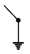
Fig. 1: Earthing Switch
Continue reading What is Earthing Switch? Working, Symbol, Installation & Function
Reactance relay is over current relay with directional restraint. The current polarizing flux goes from upper polarizing coil magnet to lower electromagnet through cylinder and iron core. So due to this flux current is induced in the cylinder whose direction is perpendicular to the plane of this paper. And it flows up and down at the sides of cylinder which are opposite of the other two poles (i.e. operating coil magnet pole and restraining coil magnet pole).
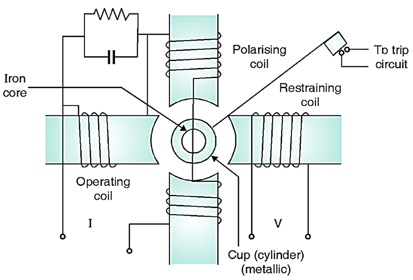
Fig. 1: Reactance relay
Continue reading What is Reactance Relay? Theory, Diagram, Torque Equation & Characteristics
The impedance relay is not normally used because of need of a separate directional unit. So mho type relays are normally used. Working is similar to impedance relay. It is made directional by providing polarising winding so torque produced is polarizing flux times fluxes from (opposed) I and V poles as shown in Fig. 1.
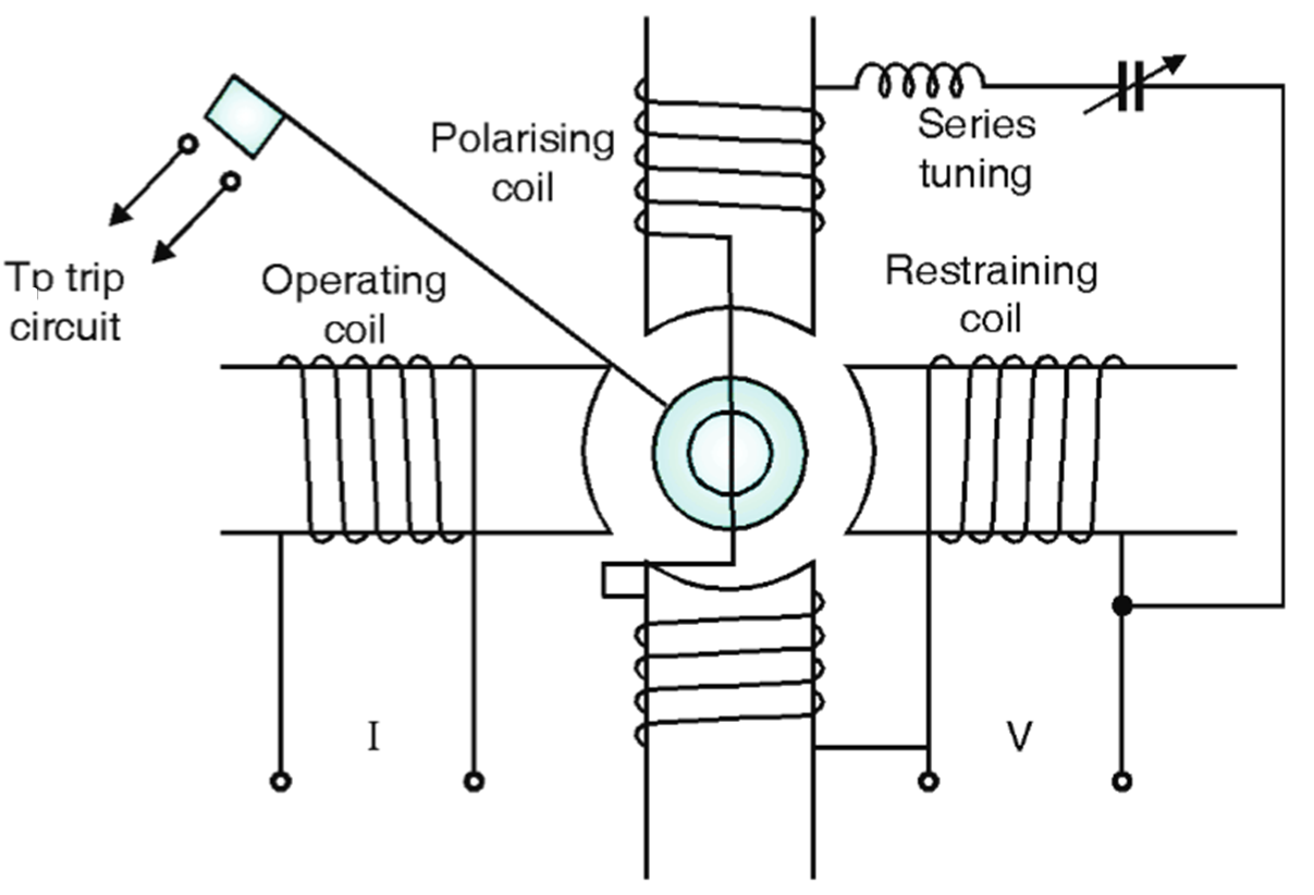
Fig. 1: MHO Relay.
Continue reading What is MHO Relay? Theory, Diagram, Torque Equation & Characteristics