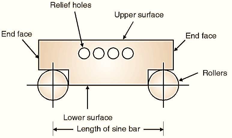
What is Sine bar? Working Principle, Construction, Diagram & Measurement Procedure

What is Sine bar Working Principle, Construction, Diagram & Reading Procedure

Figure 1: Sine bar.

Sine bar is used for measurement of angle of given job or for setting an angle, sine bar is one of the famous instrument for angle measurement. It can be used in combination of slip gauge set and dial gauge for measurement of angle. It is as shown in Fig. 1, which consists of two rollers of same diameters fixed at a distance (L) between them, called as length of sine bar.

Continue reading What is Sine bar? Working Principle, Construction, Diagram & Measurement Procedure

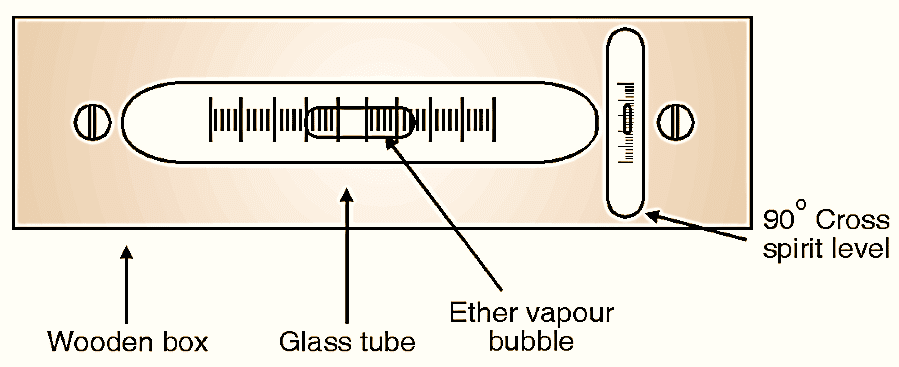
What is Micrometer? Working Principle, Construction, Diagram & Reading Procedure

Micrometer

Figure 1: Micrometer.

Micrometer screw gauge works on the principle of nut and bolt. It consists of an accurate screw with about 10 or 20 threads per cm and revolves in a fixed nut. The rotation of thread is measured, which is already calibrated. Continue reading What is Micrometer? Working Principle, Construction, Diagram & Reading Procedure

What is Parkinson’s Gear Tester (Gear Rolling Tester)? Working Principle, Construction, Diagram & Measurement Procedure
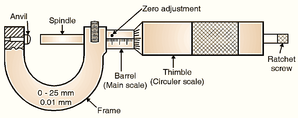
Parkinson's Gear Tester

Figure 1: Parkinson’s Gear Tester.

Instead of measuring individual errors in gears, composite errors are checked. The composite error indicates the combination of errors in a gear. In Parkinson’s Gear Tester, the gear to be tested is rolled in mesh with a master gear and the errors will be indicated by dial gauge or recording unit. Continue reading What is Parkinson’s Gear Tester (Gear Rolling Tester)? Working Principle, Construction, Diagram & Measurement Procedure
What is Tool Maker’s Microscope? Working Principle, Construction, Diagram & Measurement Procedure
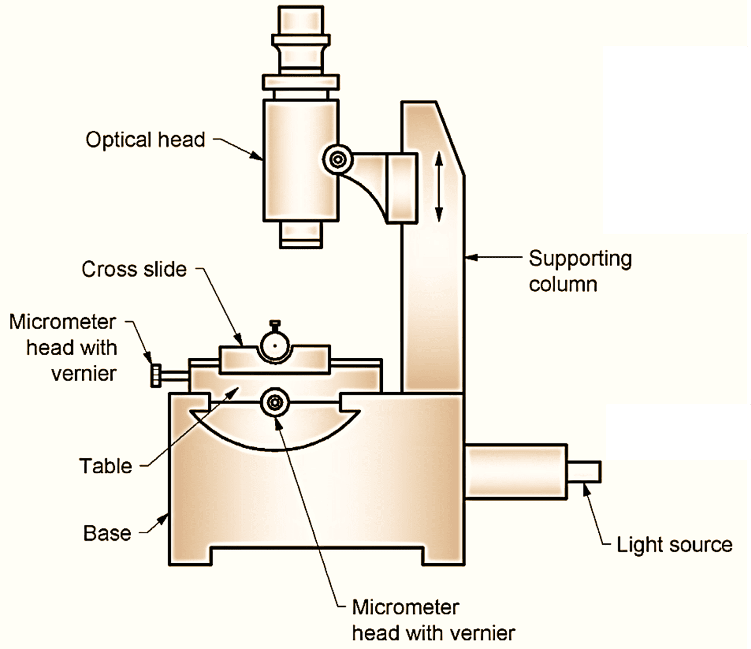
What is Tool Maker's Microscope Working Principle, Construction, Diagram & Measurement Procedure
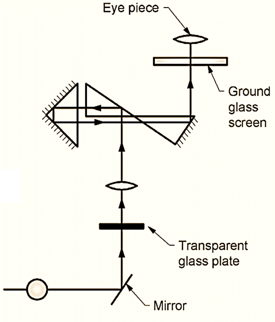
 

What is Tool Maker's Microscope

Figure 1: Tool Maker’s Microscope.

Tool Maker’s Microscope is a direct reading measuring instrument used extensively in the shop for inspecting gauges, tools, screw threads, jigs, dies, and fixtures. The essential features of the microscope are shown in Fig. 1. Continue reading What is Tool Maker’s Microscope? Working Principle, Construction, Diagram & Measurement Procedure
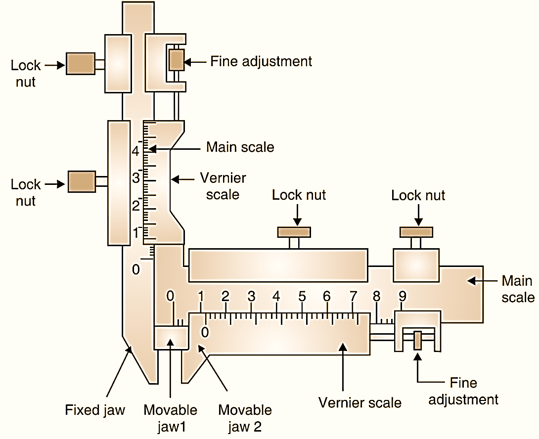
What is Gear Tooth Vernier Caliper? Working Principle, Construction, Diagram & Measurement Procedure
What is Gear Tooth Vernier Caliper Working Principle, Construction, Diagram & Measurement Procedure
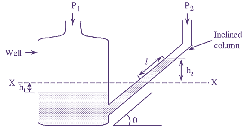
Figure 1: Gear Tooth Vernier Caliper.

The gear tooth thickness measuring vernier is as shown in Fig. 1. It measures the thickness of the tooth on pitch circle i.e. chordal thickness. Continue reading What is Gear Tooth Vernier Caliper? Working Principle, Construction, Diagram & Measurement Procedure
What is Dead Weight Tester? Construction, Working, Diagram & Calibration Procedure

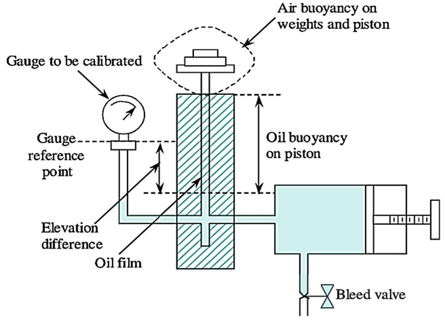
A dead weight tester is commonly used as a source of standard pressure for calibration purposes. It is basically a pressure producing and pressure measuring device.

Construction & Working Dead Weight Tester

A typical dead weight or piston gauge is schematically shown in the following figure 1,

Dead Weight Tester

Figure 1: Dead Weight Tester. Continue reading What is Dead Weight Tester? Construction, Working, Diagram & Calibration Procedure

What is Inclined Tube Manometer? Working, Construction, Diagram, Derivation & Formula

An inclined tube manometer is a cistern or well type manometer having an inclined column. It is also known as ‘draft gauge’. The schematic of an inclined tube manometer is shown in figure 1.

Inclined Tube Manometer

Figure 1: Inclined Tube Manometer. Continue reading What is Inclined Tube Manometer? Working, Construction, Diagram, Derivation & Formula