VI Characteristics of PN Junction Diode – Explanation & Diagram

Diode is the most fundamental two terminal non-linear circuit element. The relationship between the current flowing through the diode and the voltage appearing across it is nonlinear. In other words, the diode has non-linear V-I characteristics.
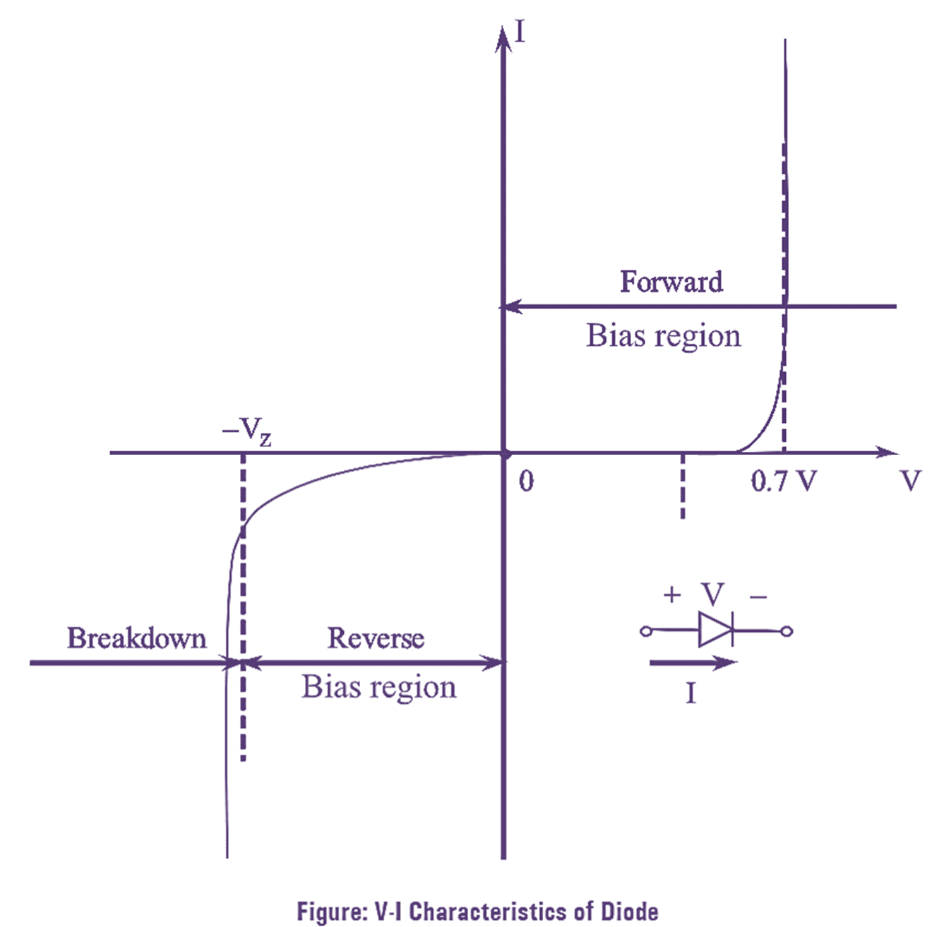
VI Characteristics of PN Junction Diode

Continue reading VI Characteristics of PN Junction Diode – Explanation & Diagram
What is Transistor Biasing? Circuit Diagram & Types (Fixed Bias, Collector to Base Bias, Voltage Divider Bias)

For the transistor to act as an amplifier is must be operated in its active region. The method of applying external voltages to operate the transistor in the active region is known as Transistor Biasing. For achieving a perfect amplification in amplifier circuit proper biasing is needed. Continue reading What is Transistor Biasing? Circuit Diagram & Types (Fixed Bias, Collector to Base Bias, Voltage Divider Bias)

What is Common Emitter (CE) Configuration of Transistor? Circuit Diagram, Derivation, Input & Output Characteristics

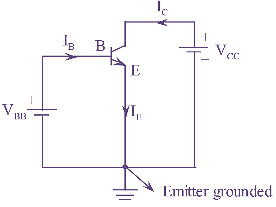
Common Emitter (CE) Configuration

Figure 1: Common Emitter (CE) Configuration.

The configuration in which emitter is common to both sides of configuration is known as common emitter configuration. Continue reading What is Common Emitter (CE) Configuration of Transistor? Circuit Diagram, Derivation, Input & Output Characteristics

What is Common Base (CB) Configuration of Transistor? Circuit Diagram, Derivation, Input & Output Characteristics

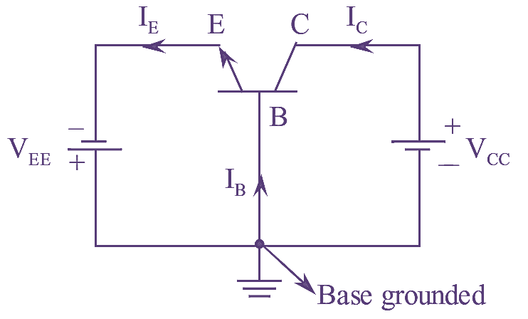
Common Base (CB) Configuration

Figure 1: Common Base (CB) Configuration.

The configuration in which base is common to both the input and output sides is known as ‘common base configuration’. Continue reading What is Common Base (CB) Configuration of Transistor? Circuit Diagram, Derivation, Input & Output Characteristics

What is Voltage Follower using Op-Amp? Circuit Diagram, Derivation & Working

The circuit in which output voltage is exactly equal and in-phase with its input, then the circuit is known as voltage follower.

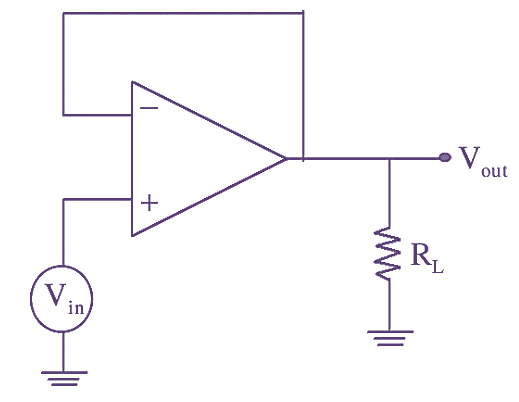
A non-inverting amplifier, whose gain is equal to 1, acts as a voltage follower. The circuit includes an op-amp and a wire connecting the output and input terminals. A non- inverting amplifier configured as voltage follower is illustrated in figure below.

Voltage Follower

Figure 1: Voltage Follower. Continue reading What is Voltage Follower using Op-Amp? Circuit Diagram, Derivation & Working

What is RC Phase Shift Oscillator? Circuit Diagram, Working & Frequency Formula

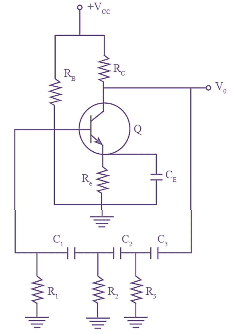
In RC Phase Shift Oscillator, the oscillations are developed due to the resistor and capacitor, which determines the frequency of oscillations.

RC Phase Shift Oscillator

Figure 1: RC Phase Shift Oscillator. Continue reading What is RC Phase Shift Oscillator? Circuit Diagram, Working & Frequency Formula

What is Negative Feedback Amplifier? Block Diagram, Gain Formula & Advantages

Negative Feedback Amplifier

Figure 1: Negative Feedback Amplifier.

The concept of feedback plays a significant role in electronic components. The basic parameters namely input impedance, output impedance, bandwidth, current or voltage gain can be varied accordingly with the help of feedback, figure 1 illustrates the block diagram of an amplifier with feedback. Continue reading What is Negative Feedback Amplifier? Block Diagram, Gain Formula & Advantages