In complementary (or class C) commutation, the SCR carrying load current is commutated (turned-OFF) by transferring its load current to another incoming SCR. The SCR to be commutated is called main SCR and the additional SCR used for commutating the conducting SCR is called complementary SCR. In this technique of commutation, both the SCRs conduct the load current alternately.
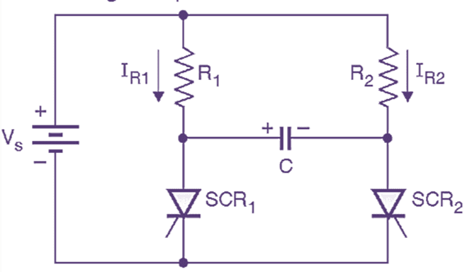
Fig. 1: Circuit diagram of complementary voltage commutation (class C commutation).
The circuit diagram for the complementary voltage commutation is as shown in Fig. 1. Both the thyristors SCR1 and SCR2 are capable of handling the load current. C is the commutating capacitor and the voltage across it is used to commutate the conducting SCR. In this way, class C commutation is voltage commutation.
The resistors R1 and R2 are load resistors and let IR1 and IR2 be the corresponding load currents such that
\[{{\text{I}}_{\text{R1}}}=\text{ }\frac{{{\text{V}}_{\text{S}}}}{{{\text{R}}_{\text{1}}}}\]
And
\[{{\text{I}}_{\text{R2}}}=\text{ }\frac{{{\text{V}}_{\text{S}}}}{{{\text{R}}_{\text{2}}}}\]
We assume that both the SCRs are ideal. Therefore the on state voltage drop across them will be zero.
Class C Commutation Operation of the circuit
The operation of complementary commutation circuit can be explained by dividing one cycle of operation into four intervals or modes of operation.
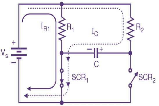
(a) Equivalent circuit for mode I
(b) Equivalent circuit for mode II
Fig 2: Equivalent circuit
Before SCR1 is triggered at instant t0 assume that SCR2 is conducting. The voltage across the commutating capacitor is equal to VS with the polarities of voltage as shown in Fig. 2(a). The load current IR2 flows through SCR2.
Mode I (t0 to t1):
At the instant t = t0, SCR1 is triggered. This connects the commutating capacitor C across the conducting SCR2. The voltage across C reverse biases the conducting SCR2 and it is turned off due to voltage commutation. The load current IR1 which is equal to VS / R1 starts flowing through SCR1. The charging current of the capacitor IC also flows through SCR1 as shown in Fig. 2(a). At t = t1 the capacitor is fully charged with polarities as shown in Fig. 2(b), and IC = 0. SCR1 continues to conduct.
Mode II (t1 to t2):
At t = t1, the charging current of the capacitor C goes to zero. The voltage on C is equal to VC with the polarities as shown in Fig. 1.26.6(b). SCR1 continues to conduct the load current IR1 = VS / R1. At the end of this mode i.e. at t = t2 the other thyristor SCR2 is triggered to turn off SCR1.
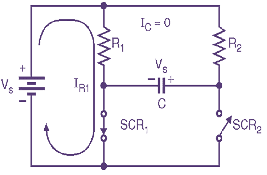
Mode III (t2 to t3):
(a) Equivalent circuit for mode III
(b) Equivalent circuit for mode IV
Fig 3: Equivalent circuit
At instant t = t2, SCR2 is turned on. This will connect the commutating capacitor C across SCR1 via SCR2. The voltage on C reverse biases SCR1 and turns it off, due to voltage commutation. The current through SCR2 i.e. ISCR2 is the sum of the load current IR2 and the charging current of capacitor IC as shown in Fig. 3 (a). The voltage across SCR1 will follow the variations in the capacitor voltage. At the end of this mode (t = t3), the capacitor is fully charged, IC = 0 and VSCR1 = VS.
Mode IV (t3 to t4):
In this mode of operation, SCR2 continues to carry the load current IR2 = VS / R2. The voltage on C is held constant equal to V with the polarities as shown in Fig. 3 (b). The charging current of the capacitor IC is equal to zero. At instant t4, SCR1 is triggered again to turn off SCR2 and the cycle of operation repeats itself.
For successful commutation, the time for which the outgoing SCR is reverse biased (tc) as shown in Fig. 4, must be greater than the turn off time of the SCR i.e. (tq).
Class C Commutation Waveforms
The input and output waveforms are as shown in Fig. 4.
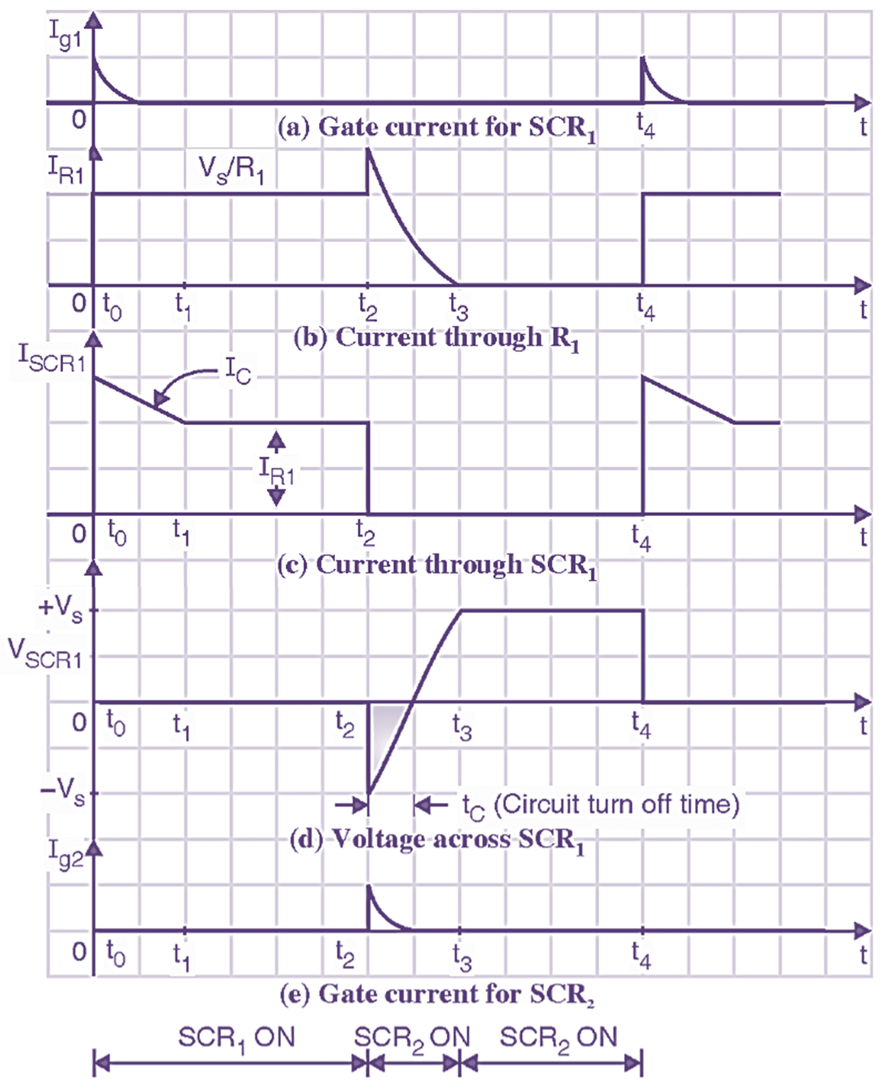
Fig. 4: Waveforms of class-C commutation.
Class C Commutation Advantages
The advantage of class-C commutation method of an SCR is as under:
- The charging current flowing through the capacitor does not flow through the load.
Class C Commutation Drawbacks
The drawbacks of class-C commutation method of an SCR are as under:
- The capacitor C can be charged to the voltage limited to the supply voltage and not more than that of it.
- The turn-ON time of the main SCR is limited due to limit on supply voltage. In high current applications, it requires high value of turn-ON time.