The auxiliary voltage commutation is also called as “Impulse commutation”, or class D commutation. The circuit diagram for class D type commutation is as shown in Fig. 1(a). SCR1 is the main load carrying SCR whereas SCR2 is an auxiliary SCR which is turned on to turn off the main SCR. Auxiliary SCR is a low-power device. The auxiliary SCR, i.e. SCR2 is turned on first in order to charge the commutating capacitor C with the polarities as shown in Fig. 1(b). As soon as C is charged, SCR2 will turn off due to a lack of current. Thus SCR2 gets commutated naturally. This positive voltage will then be held on the commutating capacitor, as there is no discharge path for it.
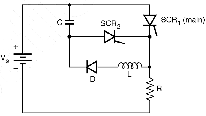
(a) Circuit diagram for auxiliary voltage commutation.
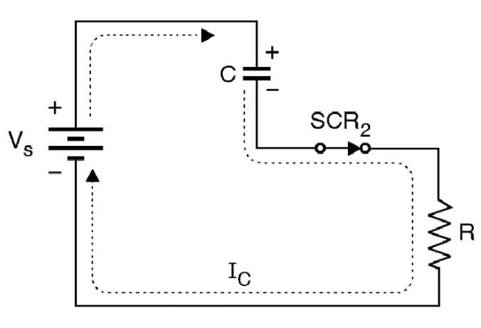
(b) Equivalent circuit before mode I
Fig. 1: Auxiliary Voltage Commutation
Operation of the circuit:
Mode I (t0 to t1):

Fig. 2: Equivalent circuit for mode I
The main thyristor SCR1 is triggered at an instant t0. As shown in Fig. 2 there are two different currents flowing in the circuit, the load current IR and the discharge current of the capacitor IC which is sinusoidal in nature. The current through the main thyristor is the sum of these two currents.
ISCR1 = IR + IC …(1)
The positive voltage on the capacitor decreases first to zero and then the capacitor is charged with a reverse polarity (See Fig. 3). When voltage on the capacitor reverses its polarity completely, the discharge current IC goes to zero at t = t1.
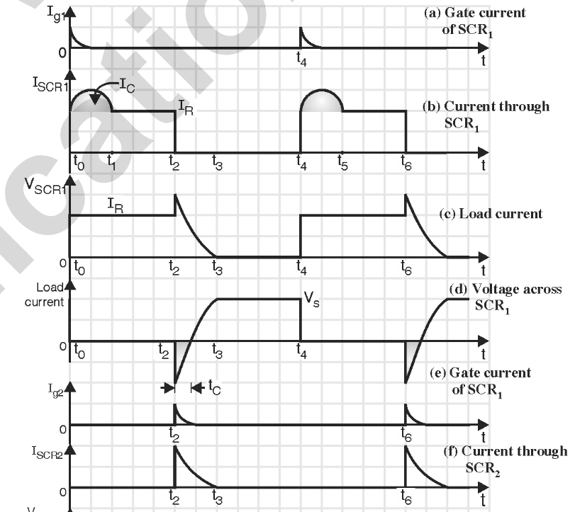
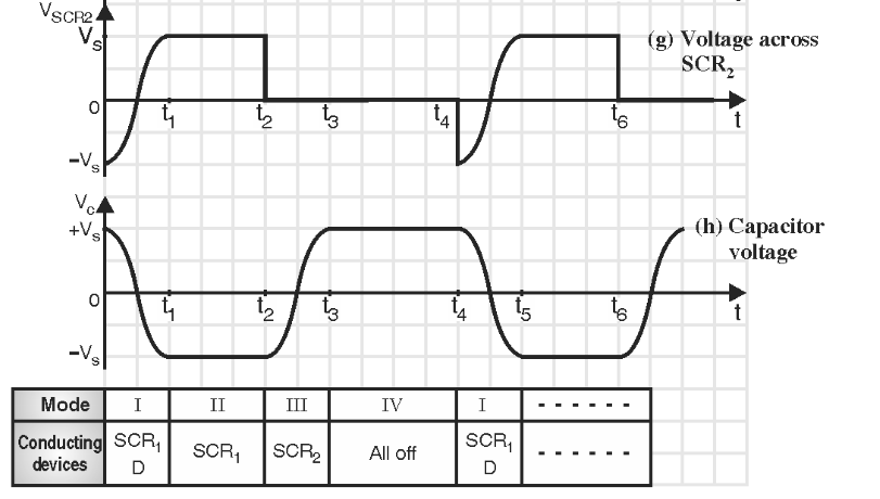
Fig. 3: Voltage and current waveforms for auxiliary voltage commutation (class D commutation)
Mode II (t1 to t2):
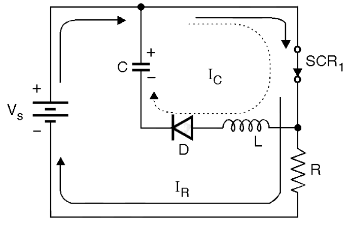
Fig. 4: Equivalent circuit for mode II
The negative voltage on the capacitor is held constant as the “hold off” diode D is now reverse biased. SCR1 continues to conduct the load current. See Fig. 4. At the instant t2 the auxiliary SCR2 is triggered in order to turn off the main thyristor SCR1 (See Fig. 3).
Mode III (t2 to t3) :
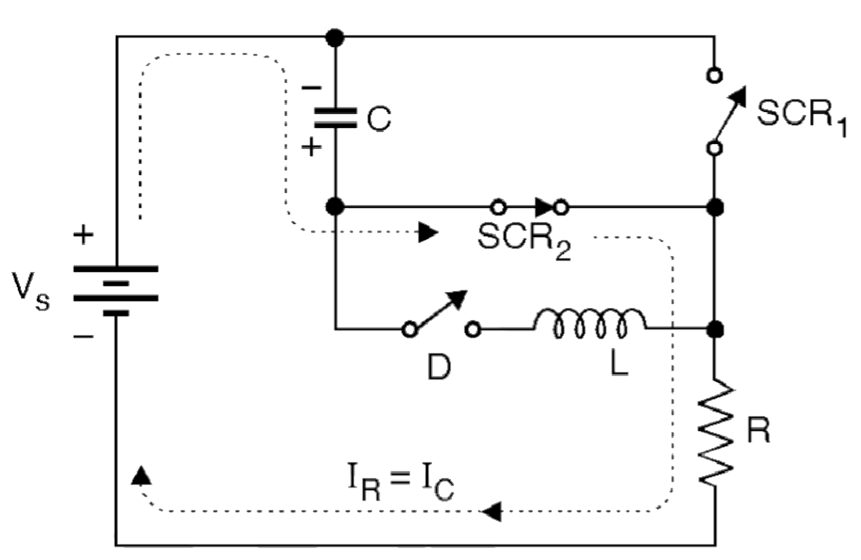
Fig. 5: Equivalent circuit for mode III
At instant t2, the auxiliary thyristor SCR2 is turned on. This connects the negative capacitor voltage (Fig. 5) across the conducting main thyristor SCR1 via SCR2. The main thyristor SCR1 is turned off due to reverse voltage applied across it.
Thus auxiliary commutation is a “voltage commutation”. Now the capacitor starts charging through SCR2 and R as shown in Fig. 4. The load current IR is equal to the capacitor charging current IC. The voltage on the capacitor increases towards zero first and then towards the positive maxima (See Fig. 3).
At the end of this mode, the voltage across the capacitor is positive, SCR2 is turned off at “t3” as the current through it goes to zero.
The voltage across SCR1 will be nothing else but VC as the capacitor is connected across SCR1 via SCR2 throughout this mode. The capacitor current and the load current go to zero at instant t3.
Mode IV (t3 to t4) :
In this mode, all the devices will remain in their off state. The positive voltage on the commutating capacitor will be held constant as there is no discharge path for the capacitor.
At instant t4 the main SCR is turned on and the cycle repeats itself. The voltage and current waveforms for auxiliary voltage commutation are shown in Fig. 3.