Single Phase Full Wave Controlled Rectifier with RL load consists of four thyristors T1 to T4 and they are connected in bridge configuration driving a highly inductive load. Fig. 1 (a) shows the circuit of single-phase fully controlled bridge rectifier with highly inductive load.
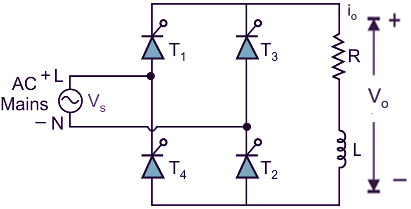
(a) Circuit diagram.
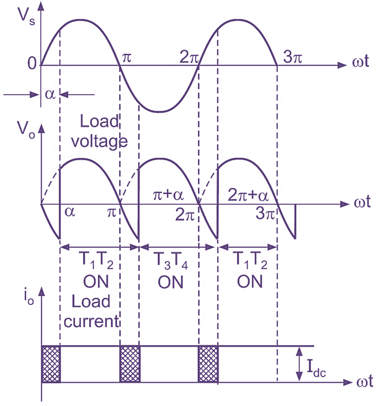
(b) Input and output voltage and current waveforms.
Fig. 1: Single Phase Full Wave Controlled Rectifier with RL load
Single Phase Full Wave Controlled Rectifier with RL load Operation
The operation of single-phase fully controlled converter consists of four modes as follows:
Mode 1 🙁 α to π):
During positive half cycle of AC input voltage, leave point L is positive with respect to cathode, therefore thyristors T1T2 are fired at ωt = α. Thus, the average output voltage is equal to the instantaneous supply voltage.
In this mode of operation, the shape of load voltage is identical to that of supply voltage. The load voltage is positive and constant. The load current i0 is also positive as that of the supply current. Both load voltage and load current are positive, the inductive load will store energy.
Mode 2: (π to π + α):
In this step of operation, at instant ωt = π, the supply goes through zero and after π radians supply reverses its polarities and it becomes negative. Therefore, the conducting thyristors T1 and T2 will try to turn-off due to natural reversal of supply voltage (i.e. natural commutation or line commutation). But due to stored energy in inductive load, it will oppose any change in the current flow through load. So thyristors T1 and T2 will continue to conduct in negative half for some period. In this mode of operation, the load voltage becomes negative and load current is always positive, continuous and constant. Both load voltage and load currents are opposite in polarities. So the stored energy in inductive load will return back to the supply again.
Mode 3: (π + α to 2π):
At instant ωt = π + α, the conducting thyristors T1 and T2 are turned off due to natural or line commutation, at the same time other pair of SCRs T3 and T4 are fired at ωt = π + α. Therefore, the average output voltage is equal to the instantaneous supply voltage. The load current is instantaneously transferred from one pair of SCRs (T1, T2) to other pair of SCR (T3, T4). In this mode of operation, both load voltage and load currents are positive, the inductive load will again store energy.
Mode 4: (2π to 2π + α):
At instant ωt = 2π radians, the input voltage goes through zero after 2π it becomes positive. i.e. during positive half cycle of AC input, the conducting thyristors T3, T4 try to turn off, the inductive load will oppose any change in current through it, in order to maintain the load current constant and in some direction, a self-induced voltage appears across the load. This maintains conducting thyristors T3 and T4 forward biased, in spite of the change in the polarity of supply voltage. The load voltage becomes negative and equal to the supply voltage whereas the load current continues positive. Therefore, load acts as a source and the stored energy in inductive load will be returned back to supply again.
Formulas of Single Phase Full Wave Controlled Rectifier with RL load
Average value of output voltage (V0)
\[{{\text{V}}_{\text{0}}}=\frac{\text{2}{{\text{V}}_{\text{m}}}}{\text{ }\!\!\pi\!\!\text{ }\text{ }}\cos \alpha \]
RMS value of output voltage (Vrms)
\[{{\text{V}}_{\text{rms}}}=\frac{{{\text{V}}_{\text{m}}}}{\sqrt{2}}\]