Brake Power is defined as the net power available at the shaft and is indicated by B.P. It is most important among all the measurements of I.C engine as it involves the measurement of torque and angular speed of the engine output shaft. The different arrangements used for measuring the B.P are as follows.
Rope Brake Dynamometer
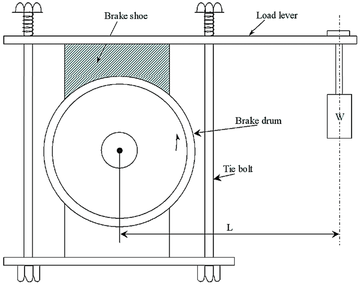
Figure 1: Rope Brake Dynamometer.
Consider a rope brake dynamometer consisting of a rope warped around the circumference of the flywheel of the engine as shown in figure 1.
The spring balance is attached to one end of the rope and the other end carries a load (W). The friction produced between the rim and the wheel absorbs the whole power developed by the engine. Due to the friction, heat is developed which inturn increase temperature of the brake wheel. Therefore, means of cooling (water) is provided to reduce the temperature of the wheel.
Let,
W – Load applied at the end of the rope in N
S – Spring balance reading in N
N – Speed of the engine in r.p.m
D – Diameter of the brake wheel in m
d – Rope diameter in m
Braking torque,
T = Friction force × Effective radius
\[=\text{(W}-\text{S})\left( \frac{\text{D}+\text{d}}{\text{2}} \right)\]
Power developed = Frictional torque × Angular rotation
\[=\text{(W}-\text{S)}\left( \frac{\text{D}+\text{d}}{\text{2}} \right)\left( \frac{\text{2 }\!\!\pi\!\!\text{}\!\!\omega\!\!\text{ }}{\text{60}} \right)\text{ W}\]
\[=\frac{\text{ }\!\!\pi\!\!\text{ N}(\text{W}-\text{S)}(\text{D}+\text{d)}}{\text{60}}\text{ W}\]
\[=\frac{\text{ }\!\!\pi\!\!\text{ N}(\text{W}-\text{S)}(\text{D}+\text{d)}}{\text{60 }\!\!\times\!\!\text{ 1000}}\text{ kW}\]
If d is neglected, then
\[\text{B}\text{.P}=\frac{\text{ }\!\!\pi\!\!\text{ DN}(\text{W}-\text{S)}}{\text{60 }\!\!\times\!\!\text{ 1000}}\text{ kW}\]
As the rope brakes are cheap and easily manufactured, they are extensively used for testing B.P of an engine.
Prony Brake Dynamometer
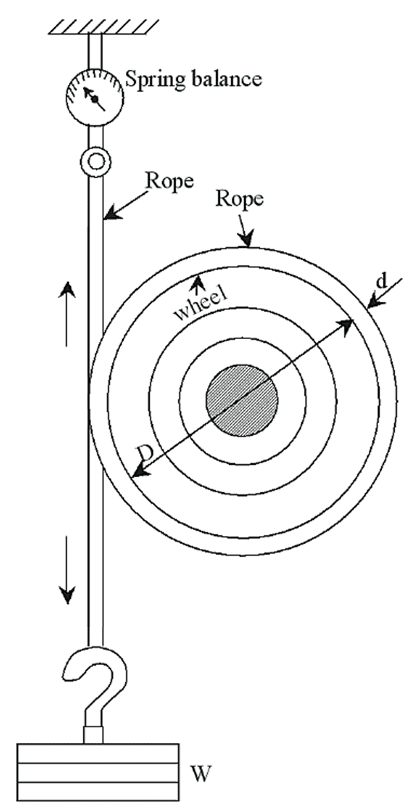
Figure 2: Prony Brake Dynamometer.
The simple arrangement of prony brake system is as shown in figure 2. The basic principle involved in the working of the prony brake is to convert the power into heat by means of dry friction. It consists of a wooden block or shoe clamped to the brake rim by means of bolts. When these blocks are pressed into contact by means of bolts, the power of the engine is dissipated in frictional resistance. The power thus absorbed is converted into heat. Due to high heat involved, these systems are provided with cooling water to cool the rim of the brake drum.
\[\text{B}\text{.P}=\frac{\text{2 }\!\!\pi\!\!\text{ NT}}{\text{60}}\text{ W}\]
Also
\[\text{B}\text{.P}=\frac{\text{2 }\!\!\pi\!\!\text{ NT}}{\text{60000}}\text{ kW}\]
Where,
T = (W × L)
W – Weight on load carrier
L – Distance from the point of load to the centre of shaft.
Prony Brake Dynamometer Advantage & Disadvantages
It has an advantage of being simple, easy to construct and inexpensive. Due to the above advantages, it is extensively used for testing of low speed engines. The main drawback of prony brake is that, it cannot be used for testing in varying conditions due to its constant torque at any one band pressure.