The LCR meter is an instrument, that can measure the value of an inductance, capacitance and resistance directly. This may be analog or digital type meter.
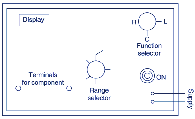
Fig. 1. Front panel of digital LCR meter
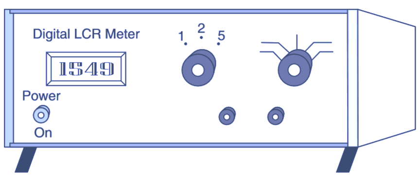
Fig. 2. Pictorial view of LCR meter
The important controls on the panel of the meter are:
Function Selector: We can select the function (L, C, R) which is to be measured.
Range Selector: We can select range (approximate) of the function under measurement.
Power Supply Switch: The supply can be switched ON and OFF by this switch. An indicator glows to indicate that the meter is connected with the supply.
The analog meter has a calibrated scale and a pointer. See Fig. 1. The digital LCR meter lias a display. See Fig. 2.
Procedure of Measurement using LCR Meter
- Connect the meter with the supply and select the position of selector switch at L. C or R according to the component under measurement.
- (Select the range by range selector.
- Connect the component across the terminals of the meter.
- On analog meter read the scale and on digital meter see the display.
LCR Meter Specification
| DISPLAY | 3 1/2 digital LED |
| MEASUREMENT FREQUENCY | DC (zero) frequency for resistance and 1 kHz for capacitance and inductance |
| RESISTANCE MEASUREMENT RANGE | 20.0 ohm to 2000 K ohm |
| RESOLUTION | 0.1 ohm on 200.0 ohm range |
| MEASUREMENT ACCURACY | ± 0.1 % of the range ± 1 digit |
| CAPACITANCE MEASUREMENT RANGE | nf to pf. |
| RESOLUTION | 0.1 pf on 200.0 pf range |