In this topic, you study Frequency Meter – Diagram, Working & Types.
Frequency Meter measures supply frequency.
Types of Frequency Meter
Frequency Meters are of two types.
- Mechanical resonance type.
- Electrical resonance type.
Mechanical Resonance Type Frequency Meter
This instrument works on the principle of mechanical resonance. It consists of a number of thin steel strips called “reeds”. These reeds are placed in a row alongside and close to an electromagnet. The reeds feel attractive force from the electromagnet and starts vibrating, the instrument, therefore, is also called as vibrating reed type frequency meter as shown in Fig. 1.
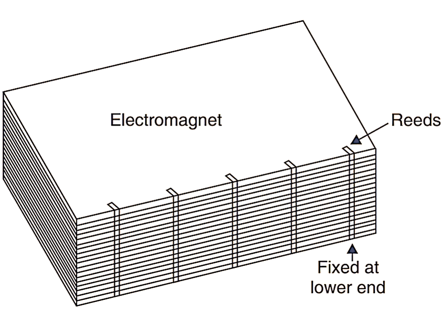
Fig. 1. Mechanical Resonance Frequency Meter.
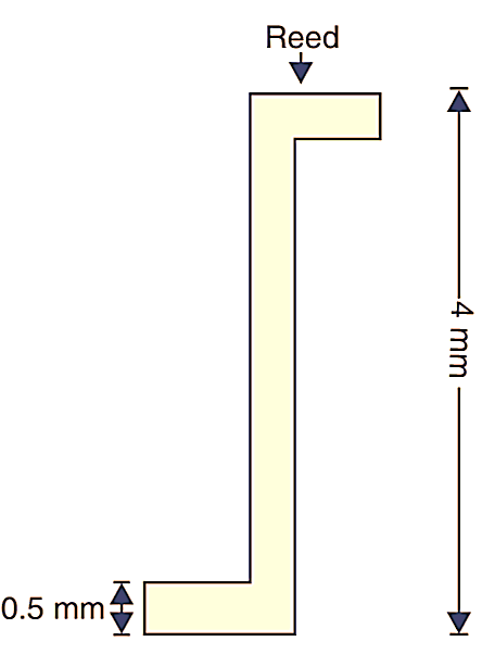
Fig. 2. Size of Reed.
The reeds have an approx. size of 4 mm x 1/2 mm thick. See Fig. 2. They however differ in size from each other and carry a white flag at their top so that their vibration can be early detected. Moreover, due to different sizes, their natural frequency of vibration also differs from each other. These reeds are arranged in ascending (increasing) order of their frequency Each successive reed has a difference of 0.5 Hz. In a frequency meter, having a range of 47 to 53 Hz will have 13 reeds having frequencies in the order of 47, 47.5, 48, 48.5, 49, 49.5, 50, 50.5, 51.51.5, 52, 52.5, and 53 HZ respectively See Fig. 3. These reeds are fixed at the bottom and are free to vibrate at their top ends.
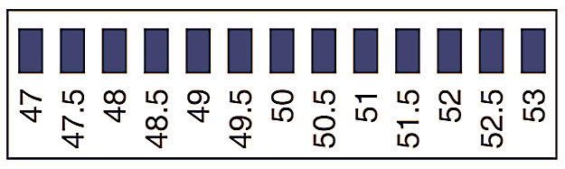
Fig. 3. Range of Frequency Meter.
Operation of Mechanical Resonance Frequency Meter
When the electromagnet is connected with the supply, its magnetism varies with the frequency of the supply all reeds experience attractive force and start vibrating. Only one particular reed, whose natural frequency becomes equal to the supply frequency comes in “mechanical resonance” and vibrates with maximum amplitudes. The frequency meter is connected across the supply, whose frequency is to be measured. The current flows through the coil of the electromagnet and the reeds feel force of attraction. The force of attraction is proportional to the square of the current, therefore it varies at twice the supply frequency and a force acts on the reeds at every half cycle. The reeds being free at their top hence start vibrating at their natural frequency as mentioned above. But a particular reed vibrates rapidly as this reed attains the resonance (Fig. 4.). The frequency opposite to this reed which is vibrating with maximum amplitude is read on the scale. The vibration of other reeds is small and almost invisible. These instruments have small range usually from 47 to 53 Hz or from 57 to 63 Hz.
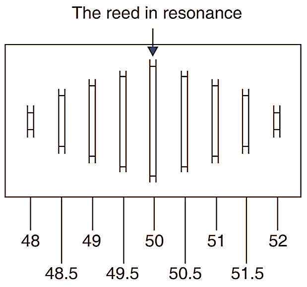
Fig. 4. Reading a Meter.
The great advantage of this instrument is that its operation is independent of wane form and magnitude of the voltage under measurement. But it cannot read less than 0.5 Hz.
Electrical Resonance Type Frequency Meter
The frequency meter works on the principle of”electrical resonance”. When inductive reactance of a circuit (XL = 2 πfL Where f is the frequency and L is inductance) becomes equal to its capacitive reactance (XC = 1/(2πfC), where c is capacitance)’ electrical resonance is said to have occurred. Note, that inductive reactance increases with the supply frequency, whereas the capacitive reactance decreases.
Construction of Electrical Resonance Type Frequency Meter
The instrument has a laminated core of varying cross-sections of the shape of a sword on one end of which a magnetizing coil is wound (Fig. 5.). The coil is fixed and is connected with the supply, whose frequency is to be measured. A moving coil is also pivoted over this iron core with a pointer which moves on a scale. A capacitor is connected, with the moving coil such that it becomes capacitive whereas the fixed coil in inductive, therefore different amount of currents flow through the coils and thus torque produced by the two currents act in opposite direction on the moving coil. The resultant torque on the moving coil is the function of the supply frequency.
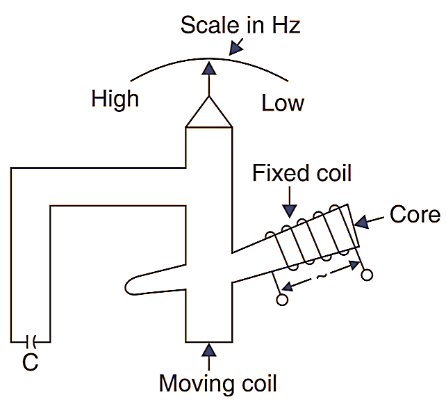
Fig. 6. Electrical Resonance frequency meter.
The controlling torque is provided by a small iron vane on the moving system. These meters are used only for power frequencies and have a range of 45 to 55 Hz. The Fig. 6. shows the dial of the frequency meter.
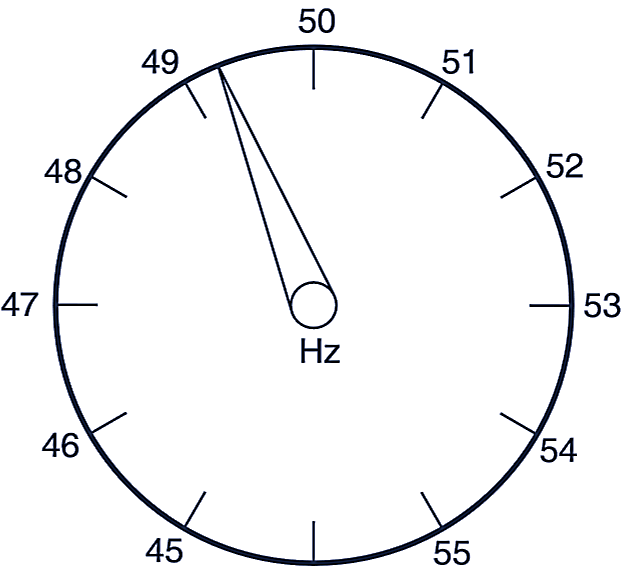
Fig. 7. Dial of the Frequency Meter.
Operation of Electrical Resonance Type Frequency Meter
The fixed coil (magnetising coil) is connected with the supply whose frequency is to be measured. The moving coil moves to a position where inductive reactance become equal to the capacitive reactance i.e., to a. position of “electrical resonance” the pointer also moves on the scale and indicates the frequency. The inductive reactance of the moving coil is dependant of its position w.r.t. to the fixed coil. Its value is maximum when it is near and minimum when it is away from the fixed coil. This has been explained below :
- When frequency increases the capacitive reactance (XC = 1/(2πfC)) decreases and the moving coil then moves away from the fixed coil and attains a position such that inductive reactance decreases and becomes equal to the capacitive reactance and resonance is established.
- When frequency decreases the capacitive reactance increases, now in this case, the moving coil moves near the fixed coil and attains a position, that inductive reactance increases and the two become again equal and resonance is reestablished.