In this topic, you study Power factor Meter – Diagram, Working & Types.
The Power factor (P.F) of a load (or a circuit) is defined as the “cosine of the phase angle” between voltage and current and it is also equal to the ratio of the true power to the apparent power. i.e.,
\[\text{P}\text{.F}\text{.}=\text{cos }\phi =\frac{\text{True power}}{\text{Apparent power}}=\frac{\text{W}}{\text{V}\text{.A}}\]
The instrument which is used to measure the power factor of the circuit is known as the power factor meter.
As the true power can be measured by a wattmeter and apparent power can be obtained by the product of voltage and current, the P.F. can be calculated by connecting a watt meter, voltmeter and an ammeter (Fig. 1.). This is a lengthy process and also involves mathematical calculations. Moreover, if P.F. is changing continuously we need a direct reading P.F. meter to read the instantaneous values.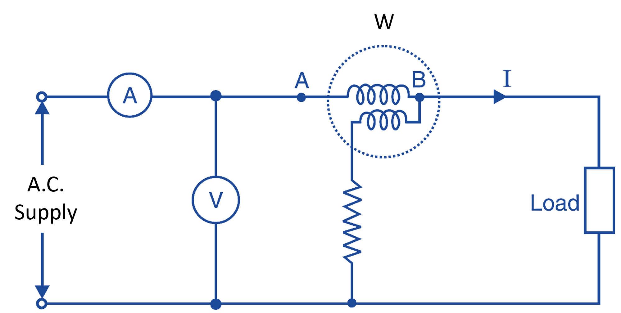
Fig. 1: Measurement of Power factor
Working Principle of Power factor Meters
Power factor meter, is in principle and construction is similar to a wattmeter having current and potential coils. The CC carries load current and PC carries a current proportional to the potential. The current coil (CC) as well as potential coil are made up of two coils. The potential coil (PC) is split into two parallel coils, one inductive and another resistive. The deflection of the instruments depends upon the phase difference between the main current (in the CC) and currents in the two branches of PC i.e., upon the P.F. of the load.
Types of PF Meters
The PF meters are of two types.
- Dynamometer type
- Moving iron type.
Both are available, we shall discuss only the first type i. e. , dynamometer type, which may be:
- Single phase.
- Three phase.
Single Phase Dynamometer Type P.F. Meter
As shown in Fig. 2, the current circuit of the instrument has two fixed coil F1 and F2, which carry the load current. The pressure circuit of the instrument has two moving coils C1 and C2 connected in parallel and fixed together at 90° to each other (Fig. 3). They are pivoted in the magnetic field of F1 and F2. The moving system is provided with a pointer which shows the deflection of a calibrated scale. When the P.F. is unity, the pointer attains a position in the centre of the scale otherwise the pointer shows lag or load value of the P.F by moving. It is important to note that a resistance R is connected in series with coil C1 so that the current through the coil is in phase with voltage of the circuit. Similarly, an inductor L is connected in series with coil C2, so that the current through this coil lags behind the emf by 90°.
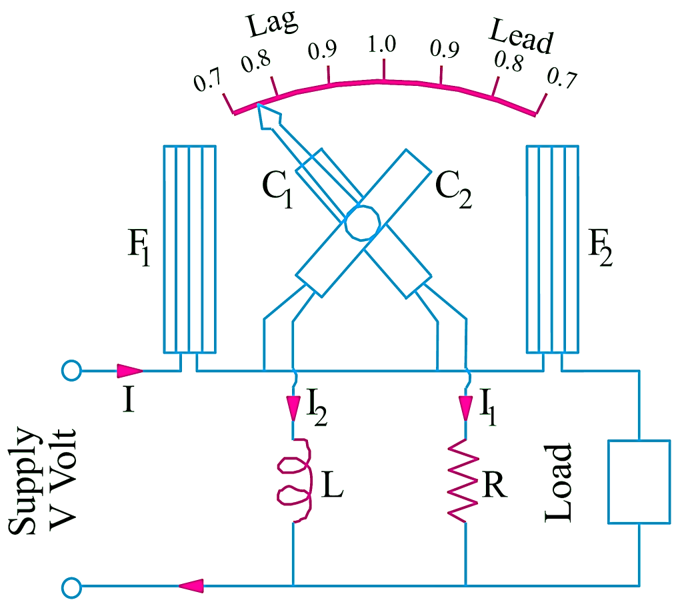
Fig. 2: Single Phase Power factor Meter
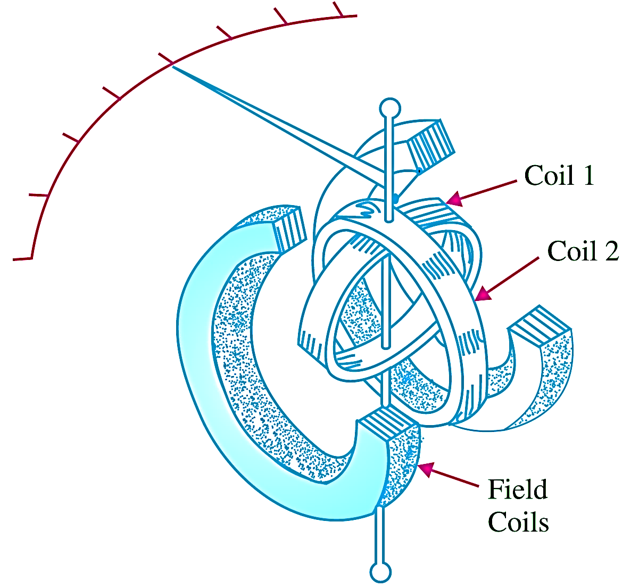
Fig. 3: Power factor Meter construction
The coils C1 and C2 are exactly similar in no. of turns and size and therefore both of them produce same amount of flux by having a phase difference of 90°. The instrument has no controlling torque, hence the pointer remains in its deflected position. Note that, “zero adjustment” is not required in these instruments.
Working of Single Phase Power factor Meter
When the instrument is connected in the circuit. the current flows through coils F1, F2, C1, and C2. The magnetic fields are produced by fixed as well as by the moving coils. The torque is produced by the principle of “alignment of two magnetic fields”. The moving coils start moving so that their magnetic fields may align with the magnetic field of the fixed coils. In this attempt, the pointer also moves and shows deflection on the scale. Note, that there will be two deflecting torques one on coil C1 and another on coil C2, and these two will be opposite in direction. Therefore, the pointer will take up a position, where the two torques are equal.
At various power factors, the operation of the instrument is described below:
Unity P.F.
In this case, the current in coil C1 lead will be in phase with the currents in F1 and F2, and the current in C2, will differ in phase by 90° from the currents in F1 and F2. The coil C1 therefore will adjust itself at perpendicular to axis of F1 and F2 and the pointer will indicate unity PF.
Lagging P.F.
In this case. booth the coils C1 and C2 would experience turning moments in opposite direction and therefore the moving system will take up an intermediate position on the lagging side between 0 and 1 depending upon the value. In majority of cases the P.F. of the load is lagging.
Leading P.F.
In this the case is reverse of (b) and the moving system takes up an intermediate position on leading side between 0 and l.
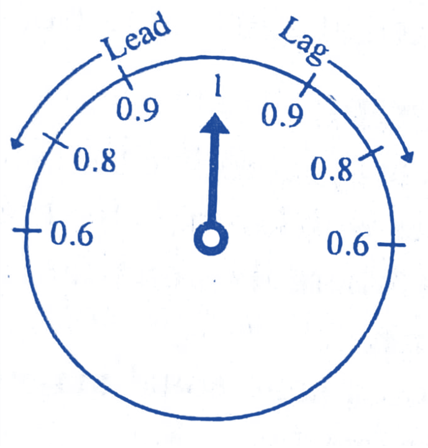
The Fig. 4 (a), show the dial of a P.F meter. The instrument is known as “phase meter” if the calibration is in angles (degree). See Fig. 4 (b).
(a)
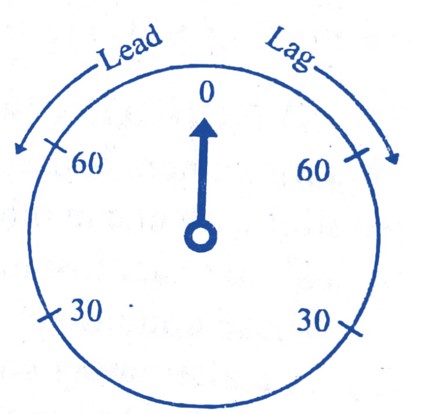
(b)
Fig. 4: Dial of a PF Meter and Phase Meter.
Three Phase Dynamometer Power factor Meter
This is used to measure P.F. of a 3 phase balanced loads (Fig. 5). Its construction is almost similar to that of a single phase Power factor meter. The two current coils (fixed coils) F1 and F2 are connected in series with one of the three phases. There are moving coils C1 and C2 arranged at 120° to one another and constitute the moving system of the instrument but they are connected across two different phases i.e., if the coil C1 is connected across the phases R and Y, the coil C2 is connected across the phase R and B. A noninductive resistance is connected in series with each of the moving coils, so that currents in both the coils are in phase with the respective emf.
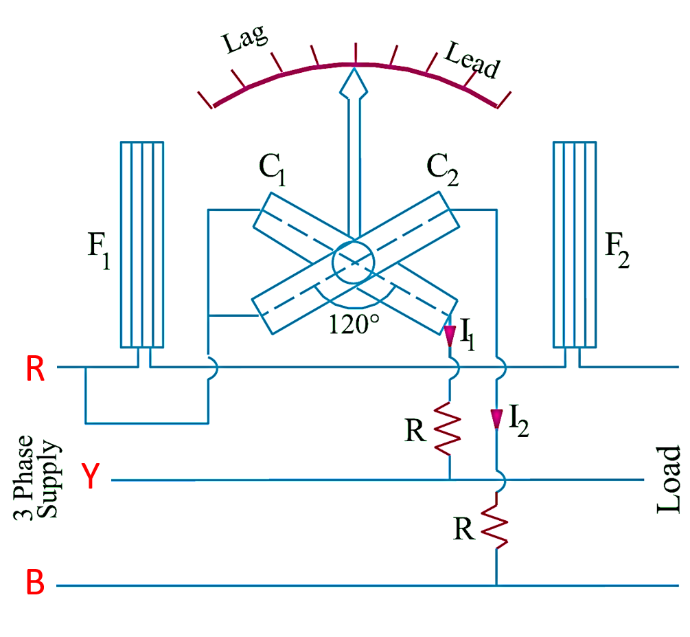
Fig. 5: Three Phase Power factor Meter
Since there is no need for phase splitting as no inductance (reactance) has been introduced in any of the moving coils, moreover, as there is no inductance (reactance) thus the operation of the instrument is independent of the frequency. But if there is any unbalancing, the accuracy will be affected.
Operation of Three Phase Power factor Meter
The operation of a 3 phase P.F. meter is same as that of the single phase P.F. meter. As no inductance has been connected in any of the moving coils, the required phase displacement between the currents in the moving coils is obtained from the supply itself.
When the instrument is connected in the circuit, the angle through which the pointer is deflected from the unity position is equal to phase angle of the circuit as the moving coils are fixed at 120° angle from each other.