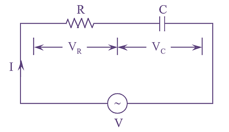
Figure (1): RC Series Circuit.
An RC series circuit consisting of a resistor ‘R’ in series with a capacitor ‘C’ connected to an A.C supply as shown in figure (l).
Application of Kirchhoff’s voltage law to the circuit shown in figure (l), we get,
\[V={{V}_{R}}+{{V}_{C}}\]
Where,
VR = Voltage drop across resistor = IR
VC = Voltage drop across capacitor = IXc
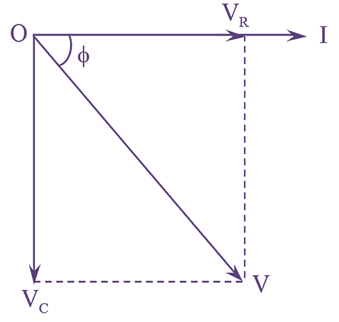
Figure (2): RC Series Circuit Phasor Diagram.
The phasor diagram is drawn taking current ‘I’ as the reference. The voltage drop VR will be in phase with current I and voltage drop VC will lagging current I by 90º. The phasor diagram is as shown in figure (2).
From the phasor diagram, we have,
\[{{V}^{2}}=V_{R}^{2}+V_{C}^{2}\]
\[={{\left( IR \right)}^{2}}+{{\left( I{{X}_{C}} \right)}^{2}}\]
\[={{I}^{2}}\left( {{R}^{2}}+X_{C}^{2} \right)\]
\[V=\sqrt{{{I}^{2}}\left( {{R}^{2}}+X_{C}^{2} \right)}\]
\[=L\sqrt{\left( {{R}^{2}}+X_{C}^{2} \right)}=IZ\]
Where
\[Z=\sqrt{\left( {{R}^{2}}+X_{C}^{2} \right)}\]
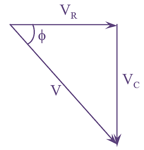
Figure (3): RC Series Circuit Impedance Triangle.
The phase angle difference $\phi$ is given by,
\[\tan \phi =\frac{{{V}_{C}}}{{{V}_{R}}}=\frac{I{{X}_{C}}}{IR}=\frac{{{X}_{C}}}{R}\]
\[\phi ={{\tan }^{-1}}\left( \frac{{{X}_{C}}}{R} \right)\]
Power factor,
\[\cos \phi =\frac{{{V}_{R}}}{V}=\frac{IR}{IZ}=\frac{R}{Z}\]
Total power,
P = VI cosϕ watts