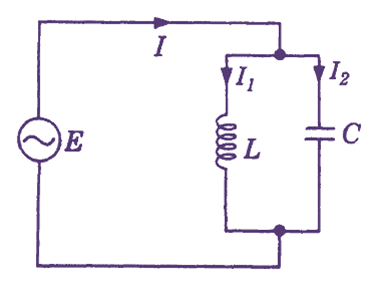
(a) Circuit Diagram
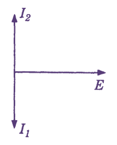
(b) Phasor Diagram
Figure 1: Parallel Resonance Circuit.
In a parallel resonant circuit, the inductor L and capacitor C are connected in parallel as shown in Fig. 1 (a). The circuit current consists of two branch currents I1 and I2. The inductive current I1 lags the voltage E by 90°. On the other hand the capacitive current I2 leads the voltage E by 90°. These currents are 180° out of phase as shown in Fig. 1 (b). The total current I equals the resultant of these current components.
i.e.
\[I={{I}_{1}}+{{I}_{2}}\]
\[I=\frac{E}{Z}\]
If XL and XC are inductive and capacitive reactances then,
\[Z=\frac{{{X}_{1}}.{{X}_{2}}}{j{{X}_{1}}-{{X}_{2}}}\]
Also
\[Z=\frac{j\omega L.\frac{1}{j\omega C}}{j\left( \omega L-\frac{1}{\omega C} \right)} …(1)\]
At resonant frequency fr,
\[\omega L=\frac{1}{\omega C}…(2)\]
Substituting this value in Eq. 1, we obtain,
\[Z=\frac{L/C}{0}=\infty \]
Solving Eq. 2
\[\omega L=\frac{1}{\omega C}\]
\[{{f}_{r}}=\frac{1}{2\pi \sqrt{LC}}\]
In practice, the inductance L always has a small internal resistance which must be taken into account. The impedance of the circuit including R is, therefore, given by
\[Z=\frac{\left( R+j\omega L \right)\frac{1}{j\omega C}}{R+j\left( \omega L-\frac{1}{\omega C} \right)}…(3)\]
At resonant frequency fr, R << ωL. Therefore it can be neglected from the numerator.
Also
\[\omega L=\frac{1}{\omega C}\]
Substituting these values in Eq. 3 gives the impedance of a parallel resonant circuit as,
\[Z=\frac{L/C}{R}\]
\[Z=\frac{L}{CR}=\frac{{{\omega }_{r}}L}{{{\omega }_{r}}CR}={{\omega }_{r}}.L.Q\]
And resonant frequency
\[{{f}_{r}}=\frac{1}{2\pi \sqrt{LC}}\]
At resonance, the circuit offers maximum impedance. This impedance falls above and below the resonant frequency. To understand about variation of impedance of a parallel resonant circuit, consider Eq. (3) once again
\[Z=\frac{\left( R+j\omega L \right)\frac{1}{j\omega C}}{R+j\left( \omega L-\frac{1}{\omega C} \right)}\]
The denominator of this expression gives the impedance of a circuit in which elements L, C and R and connected in series. Thus if we denote this impedance as ZS, (Since, R << jωL) then Eq. (3) may be rewritten as
\[Z=\frac{\left( R+j\omega L \right)\frac{1}{j\omega C}\approx \frac{L/C}{{{Z}_{S}}}}{{{Z}_{S}}}\]
The impedance Z of a parallel L, C and R circuit varies inversely with the series impedance ZS of the same circuit. The plot of the impedance of a parallel circuit is then just the inverted form of the plot of impedance of series circuit. The magnification factor Q of a series resonant circuit has been defined as the ratio of the voltage across inductive reactance to the voltage across resistor R. In a parallel resonant circuit, the voltage across L and C is same as the signal voltage E and the magnification factor is defined as ratio between the circulating current in inductance (IC) or capacitance (IC) to the current I drawn from the signal source.
Thus Q of a parallel resonant circuit is given as,
\[Q=\frac{{{I}_{L}}}{I}=\frac{{{I}_{C}}}{I}\]
Now
\[{{I}_{C}}=\frac{E}{{{X}_{C}}}\]
\[{{I}_{L}}=\frac{E}{{{X}_{L}}}\]
\[ I=\frac{E}{Z}\]
Therefore,
\[Q=\frac{{{I}_{C}}}{I}=\frac{E}{{{X}_{C}}}\div \frac{E}{Z}\]
\[=\frac{E.\omega C}{E}\times \frac{L}{CR}=\frac{\omega L}{R}\]
Similarly,
\[Q=\frac{{{I}_{L}}}{I}=\frac{E}{{{X}_{C}}}\div \frac{E}{L/CR}\]
\[=\frac{E}{\omega L}\times \frac{L}{ECR}=\frac{1}{\omega CR}\]
Thus,
\[Q=\frac{\omega L}{R}=\frac{1}{\omega CR}…(4)\]
From Eq. (4), we find that magnification factor of a parallel resonant circuit is given by the same expression as that of a series resonant circuit.
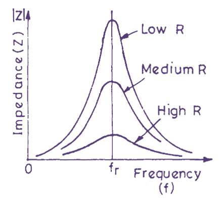
Fig. 2. Plot of impedance/frequency for a parallel resonant circuit.
The impedance versus frequency curve for the parallel circuit has the same general shape as the current/frequency of a series circuit and is shown in Fig. 2. The impedance is found to be maximum at resonance but decreases above or below resonance. If the internal resistance of the circuit is small, the impedance is large but shows a sharp decrease on both sides of the resonance frequency. The circuit is highly selective. If the internal resistance of the inductance is large, the impedance at resonance is low and impedance curve is flat.
Bandwidth of Parallel Resonance Circuit
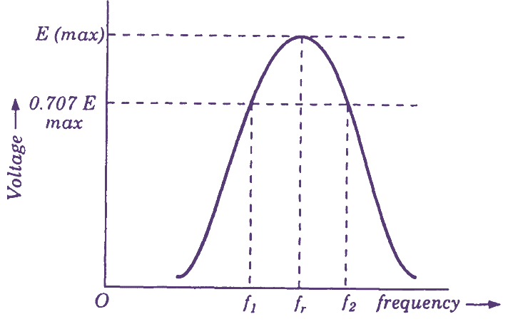
Fig. 3. Plot of voltage/frequency for a parallel resonant circuit.
If a current of varying frequency is fed to this circuit, the voltage developing across the tuned circuit will be different at different frequencies. At fr , the voltage developed will be the highest because the impedance is highest while at other frequencies, the voltage falls. This is because of fall in the circuit impedance at those frequencies. Fig. 3 shows a plot of voltage/frequency for a parallel circuit. The bandwidth may be found out by marking the frequencies at which the voltage falls to 70.7
\[BW=\frac{{{f}_{r}}}{Q}\]