The circuit in which output voltage is exactly equal and in-phase with its input, then the circuit is known as voltage follower.
A non-inverting amplifier, whose gain is equal to 1, acts as a voltage follower. The circuit includes an op-amp and a wire connecting the output and input terminals. A non- inverting amplifier configured as voltage follower is illustrated in figure below.
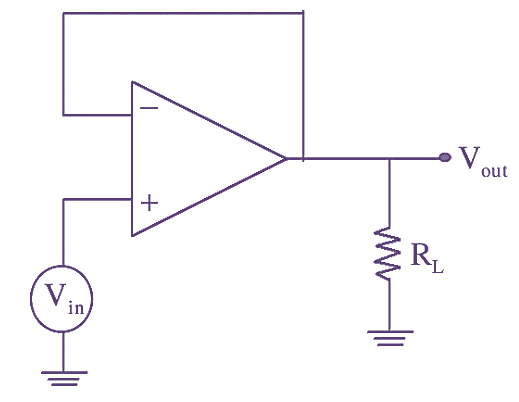
Figure 1: Voltage Follower.
In the above figure, since the complete output is feedback to the inverting input. the gain of the circuit becomes. The output voltage of a non-inverting amplifier is given by,
\[{{V}_{out}}=\left( 1+\frac{{{R}_{F}}}{{{R}_{1}}} \right){{V}_{in}}\]
Since RF = 0, R1 = ∞, we get
\[{{V}_{out}}={{V}_{in}}\]
Features of Voltage Follower
- The input impedance is high i.e., in the order of MΩ. Hence, it draws negligible current from signal source.
- Due to its low output impedance, it can be used as buffer for connecting high impedance source to a low impedance load.
- Voltage follower has large bandwidth.
- The voltage follower circuit output follows the input precisely with zero phase shift.
- It has unity gain.
Applications of Voltage Follower
In instrumentation amplifier, loading effect of transducer is eliminated by using voltage follower between transducer and amplifier.