Zero Crossing Detector (ZCD) is a basic comparator circuit, whose reference voltage level is set at zero. It detects the zero crossing in the applied input AC signal is referred to as zero crossing detector. It is also called a sine to square wave converter.
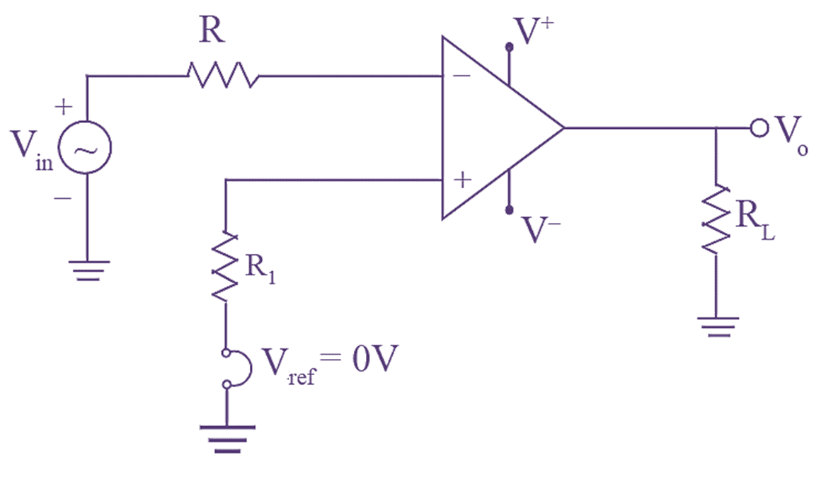
Figure 1: Zero Crossing Detector.
Working of Zero Crossing Detector
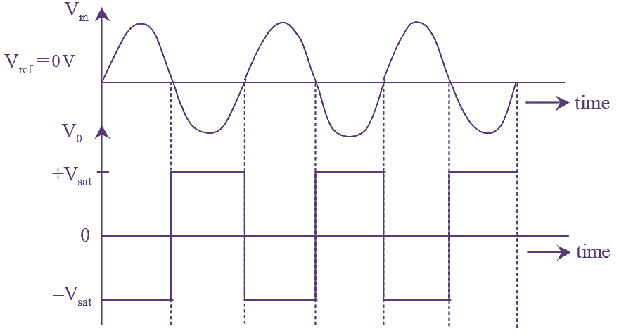
Figure 2: Zero Crossing Detector input & output waveforms.
The circuit diagram of Zero Crossing Detector using Op-Amp is shown in Figure 1. When the input signal crosses zero voltage in the negative direction the output voltage changes from negative saturation to positive saturation level. Similarly, when the input signal crosses zero voltage in the positive direction. the Output voltage changes from positive saturation to negative saturation level. For an applied input sinusoidal signal. the output signal is a square wave as shown in figure (2).
If,
${{V}_{in}}>0$ (Negative Direction)
\[{{V}_{o}}=-{{V}_{sat}}\to +{{V}_{sat}}\]
If,
${{V}_{in}}>0$ (Positive Direction)
\[{{V}_{o}}=+{{V}_{sat}}\to -{{V}_{sat}}\]
Disadvantages of Using Zero Crossing Detector
- For low frequency input signals the output voltage may not switch from one saturation voltage to another because, it takes more time for input voltage waveform to cross the zero level.
- Due to the noise entering the input terminals of op-amp. The output voltage may fluctuate between the two saturation points or voltages.
In order to overcome these two disadvantages a regenerative (i.e.. positive) feedback is to be given which makes output voltage to change rapidly and remove the output transitions due to noise at the input terminals. This regenerative feedback is employed in the Schmitt trigger.