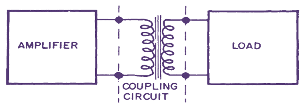
Fig. 1. Transformer coupling.
A transformer may also be used for coupling the output of an amplifier to the load as shown in Fig. 1. The transformer ensures that the AC signal is transferred to the load but the DC cannot be passed on to the secondary. The circuit is costlier than RC coupling but has the advantage that the turn ratio of the transformer can be so adjusted as to provide impedance matching and hence maximum energy transfer to the load can be ensured.
Circuit Diagram & Working of Transformer Coupled Amplifier
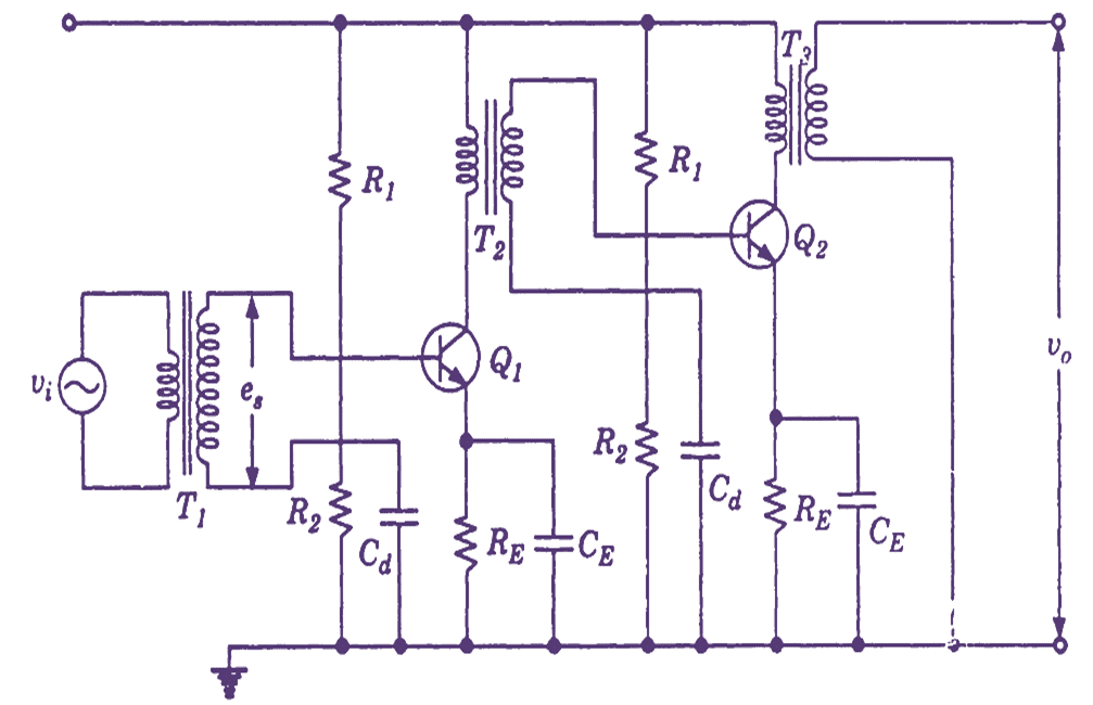
Fig. 2. A two stage transformer coupled amplifier.
In this scheme of coupling, a transformer is used to provide coupling between two amplifier stages. The primary of the transformer replaces the collector load RL of the first amplifier stage while the secondary winding of this transformer provides the signal drive to the base of the second stage. Fig. 2 shows the circuit of a two-stage transformer coupled amplifier. In this coupling scheme, coupling capacitors are not used and we use transformers. For coupling the input signal to the base of the transistor Q1 transformer T1 is used. Transformer T2 is used for inter-stage coupling between first and second stage and transformer T3 is used for delivering the Q1 output to the load. Thus, we find that transformer T1, which acts as the input transformer feeds the input signal to the base of Q1. DC bias voltage is provided to this stage by the potential divider circuit of R1 and R2 and signal voltage (es) is connected in series with this bias voltage. Capacitor Cd is shunted across R2 to ensure that from signal point of view, the junction of R1 and R2 is at ground potential and signal appears across base emitter junction of Q1.
The collector load resistor is replaced by primary of the transformer T2 which provides inter-stage coupling between Q1 and Q2 .The DC bias to the second stage Q2 is provided by a circuit that is identical to the arrangement used in Q1. The output signal is obtained by means of transformer T3 which acts as output transformer. T1 and T2 are termed as input transformer and coupling or driver transformer respectively.
Advantages of Transformer Coupled Amplifier
An important advantage of transformer coupling is that the entire DC supply V’ is available at the collector of the transistor since there is no voltage drop across the transformer secondary. In other words, the DC operating point is located at the supply point Vcc. Because of this, power loss in the collector resistor is avoided. Secondly, since complete supply voltage is present at the collector, the transformer coupled circuits are capable of operating at lower supply voltages. Thus, these circuits are commonly used in pocket transistor receivers where the supply voltage is provided by a single 1.5 volts cell.
Disadvantages of Transformer Coupled Amplifier
Apart from the advantages stated above, there are some drawbacks in the circuit using transformers. Firstly, the transformers are costlier than R-C combination. Secondly, they are bulky and increase the size of the equipment. Lastly, the transformer action takes place due to rate of change of current in the primary winding. When signal frequency is very low, the rate of change of primary current is small and the transformer action does not take place. Therefore, at these frequencies, a transformer coupled amplifier circuit does not operate satisfactorily and output is reduced. Similarly, the inter-winding inductance and capacitance of the transformers deteriorate the response of the amplifier at high frequencies.
Applications of Transformer Coupled Amplifier
Transformer coupled stages are therefore not commonly used in low frequency amplifiers. Their common use is at high frequencies – i.e. above AF range. We find transformer coupled amplifiers in all radio receiver in the form of IF amplifier with an operating frequency of about 460 KHz and also as RF amplifiers.