In this topic, you study Equivalent Circuit of Transformer.
Analysis of transformer performance can be conveniently made by using its equivalent circuit. An equivalent circuit of a transformer is that circuit whose behaviour is very similar to that of the transformer.
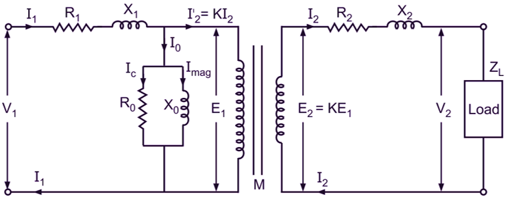
Fig. 1: Equivalent circuit of a transformer
Such an equivalent circuit can be developed by initially assuming the transformer to be an ideal one. The different imperfections of the actual transformer are then allowed for by means of additional circuits or impedances, inserting them between the supply terminals and the primary winding and between secondary terminals and the load as illustrated in Fig. 1. Here M represents the ideal transformer with no losses and no magnetic leakage and having an iron core of infinite permeability requiring no magnetizing current. R1, X1, R2, and X2 respectively represent the resistance and leakage reactance in lumped form of the primary and secondary of the actual transformer. Similarly, to account for no-load current I0 of the actual transformer, a shunt circuit consisting of R0 and X0 is introduced such that
\[\frac{{{\text{E}}_{\text{1}}}}{{{\text{R}}_{0}}}={{\text{I}}_{\text{c}}}\]
And,
\[\frac{{{\text{E}}_{\text{1}}}}{{{\text{X}}_{0}}}={{\text{I}}_{\text{mag}}}\]
where, Ic and Imag are the two quadrature components, namely the core-loss component and magnetizing component, of the no-load current of the actual transformer. The circuit so developed thus has the electrical characteristic similar to that of actual transformer and therefore is called its equivalent circuit.