In this topic, you study Open Circuit Test of Transformer.
Experimental Set-up of Open Circuit Test of Transformer
The primary of the transformer is connected across the suitable ac supply through an ammeter, a voltmeter and a wattmeter as shown in Fig. 1. The secondary of the transformer is normally kept open. However, if the turns ratio of the transformer is to be determined, then a voltmeter may be connected across the secondary terminals. Even in this case, the resistance of the voltmeter being very high, the secondary circuit is regarded as open only (i.e. without any load). In actual practice, low-voltage side is preferred for giving supply from the point of view of safety and convenience. Moreover, sometimes high voltage supply may not be available for testing purposes.
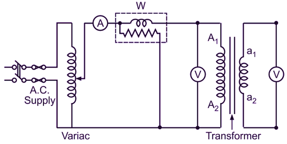
Fig. 1: Open circuit test on a transformer
Procedure of Open Circuit Test of Transformer
Voltage across the primary is adjusted to its rated value. A variac or some suitable arrangement may be used for this purpose. The readings of the various instruments are then recorded in the observation table.
Table for Observations
| Sr. No. | Primary Side | Secondary side | ||||
| V1 | Io | Wo | V2 | |||
Calculations and Results of Open Circuit Test of Transformer
The ratio of voltmeter readings, V1/V2 gives accurately the turns ratio of the transformer. The magnitude of no-load current (I0) gives a check on the magnetic quality of the iron core and joints. The reading of the wattmeter (W0) gives iron loss of the transformer. The primary current being very small, the copper loss (I2R loss) under this condition is almost negligible in comparison with the iron loss.
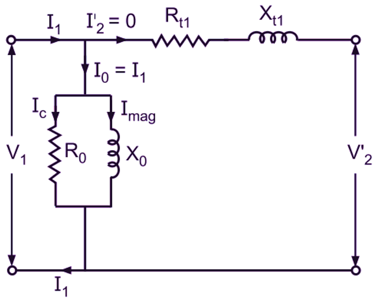
Fig. 2: Equivalent circuit of a transformer referred to the primary side under open circuit condition
The values of R0 and X0 of the shunt circuit accounting for no-load current can also be calculated from the data obtained from this test. Fig. 3 shows the equivalent circuit of a transformer referred to the primary side under open circuit condition. No-load power factor,
\[\cos {{\phi }_{0}}=\frac{{{\text{W}}_{\text{0}}}}{{{\text{V}}_{\text{1}}}{{\text{I}}_{\text{0}}}}\]
Now, from the no-load phasor diagram of Fig. 3,
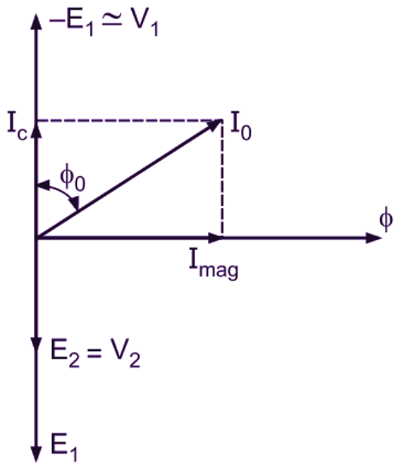
Fig. 3: Transformer no-load phasor diagram
\[{{\text{I}}_{\text{c}}}={{\text{I}}_{\text{0}}}\cos {{\phi }_{0}}\]
and
\[{{\text{I}}_{\text{mag}}}={{\text{I}}_{\text{0}}}\sin {{\phi }_{0}}\]
Hence, referring to the equivalent circuit of Fig. 2, we have
\[{{\text{R}}_{\text{0}}}=\frac{{{\text{V}}_{\text{1}}}}{{{\text{I}}_{\text{c}}}}\]
and
\[{{\text{X}}_{\text{0}}}=\frac{{{\text{V}}_{\text{1}}}}{{{\text{I}}_{\text{mag}}}}\]