In this topic, you study Short Circuit Test of Transformer.
Experimental Set-up of Short Circuit Test of Transformer
The primary of the transformer is connected across a suitable variable low-voltage ac supply through an ammeter, a voltmeter and a wattmeter as shown in Fig. 1. The secondary terminals are shorted solidly using a link of negligible resistance. The current on the high voltage side of the transformer being less, it is always convenient to connect the high voltage side to the supply and short the low-voltage side.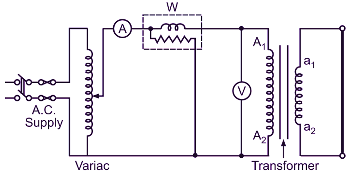
Fig. 1: Short-circuit test on a transformer
Procedure of Short Circuit Test of Transformer
The voltage applied across the primary winding is adjusted to circulate the full-load currents in the primary and secondary circuits and then the various observations are recorded in a tabular form. Since a very small voltage is required for circulating the full-load currents in both the windings, the precaution must be taken while applying this voltage. If the voltage exceeds this limit, windings may be damaged due to overheating by heavy circulating currents.
| Sr. No. | Primary Side | Secondary side | ||||
| VSC | ISC | WSC | V2 | |||
Calculations and Results of Short Circuit Test of Transformer
- Currents in both the windings being full-load currents, the wattmeter reading gives the full-load copper loss of the transformer. Voltage applied across the primary winding of the transformer being very small, the flux density in the transformer core is also very small. Hence, the iron loss of the transformer under this condition is negligibly small in comparison with its copper loss. Due to some difficulty, if the short-circuit test is conducted with currents other than full-load currents in the primary and secondary windings of the transformer, corresponding full-load copper loss can be calculated remembering that the copper loss is proportional to the square of the current.
- The total effective resistance Rt1 and leakage reactance Xt1 of the transformer referred to the primary side can be calculated from the data of this test as follows:
Fig. 2 shows the equivalent circuit of a transformer referred to the primary side under the short-circuit condition. The applied voltage being very small under short-circuit condition, the current component is negligible in comparison with the load component of the primary current. Hence, the shunt circuit consisting of and is totally omitted here. Now firstly, is found out using the relation
\[{{\text{W}}_{\text{SC}}}=\text{I}_{\text{SC}}^{\text{2}}{{\text{R}}_{\text{t1}}}\]
The total effective impedance of the transformer referred to the primary side is then calculated from the equivalent circuit shown in Fig. 2.
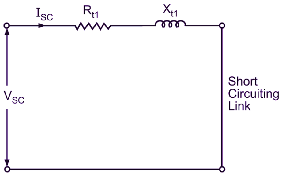
Fig. 2: Equivalent circuit of a transformer referred to the primary side under short-circuit condition
\[{{\text{R}}_{\text{t1}}}=\frac{{{\text{V}}_{\text{SC}}}}{{{\text{I}}_{\text{SC}}}}\]
\[{{\text{X}}_{\text{t1}}}=\sqrt{{{\text{(}{{\text{Z}}_{\text{t1}}})}^{2}}-{{({{\text{R}}_{\text{t1}}})}^{2}}}\]
Here, it is very important to note that in the case when the primary is shorted and the supply is given to the secondary, all the data will belong to the secondary side. Then the constants of the equivalent circuit calculated from this data will obviously refer to the secondary side only, the corresponding expressions being, The constants , , can then be referred to the primary side if required. These parameters are then used for finding the regulation of a transformer.