The windings are placed on the cores. The winding is done with the insulated copper conductors. The winding which is connected to supply is the primary winding and to which load is connected is known as secondary winding. According to the construction the windings are classified as under.
- Cylindrical type winding
- Sandwich type winding
Cylindrical type winding
The winding in which the length of the coil is equal to the length of the limb is known as cylindrical windings as shown in Fig. 1. The coils of high tension or low tension or say primary and secondary are wound keeping LT. near the cores.
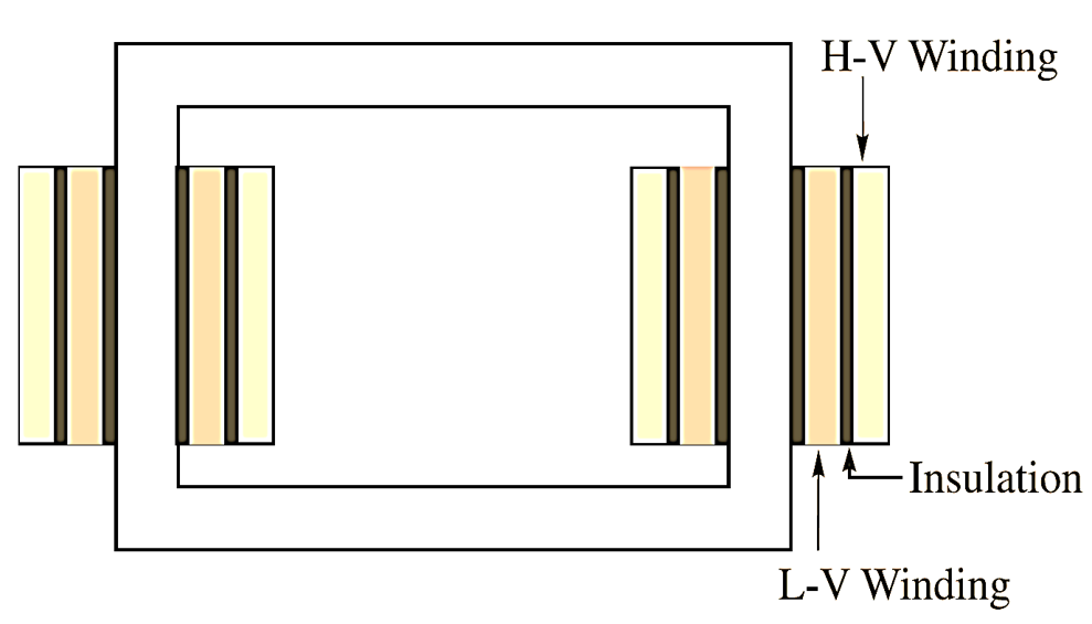
Fig. 1: Transformer Cylindrical winding
Sandwich type winding
The term is almost self explanatory in this winding the primary and secondary are placed one over the other alternately as shown in Fig. 18.3 (b).
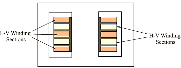
Fig. 1: Transformer Sandwich winding
These are suitably employed for the shell type transformers. The reactance is minimised in this type of winding to an appreciable limit. These are commonly used with large H.T. transformers.
Terminals and bushings
The leads of both windings are connected to the terminals so that the supply can be taken and connected to. In a small transformer of low voltage the terminals are fixed on the bakelite plate. For the transformers of high voltage ordinary porcelain insulators and bushings are used. Sometimes the oil filled bushings and condenser type bushings are also used for high voltage transformers.