In this topic, you study Wattmeter – Definition, Circuit Diagram, Symbol & Types.
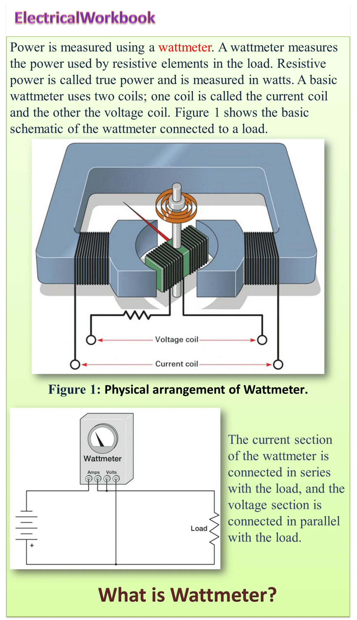
The power consumed by the electrical circuit is measured by means of wattmeter. A wattmeter has two coils: the current coil and pressure (or voltage) coil. The current coil has less resistance, less turns wound with thick conductor and connected in series with the load. The pressure coil is having more resistance wound with the conductor having more number of turns and always connected across the supply. The torque produced depends upon the flux produced by the current coil and pressure coil. Wattmeter is used for measuring electrical power.
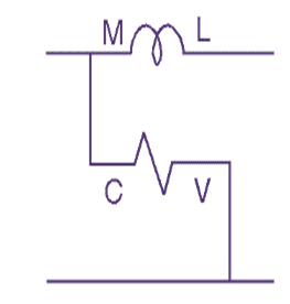
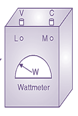
Symbol of Wattmeter
Types of wattmeter
The following are types of wattmeters:
- Electrodynamometer type
- Induction type
- Electrostatic type
Electrodynamometer Type Wattmeter
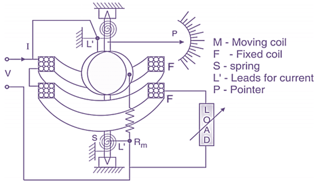
(a) Construction.
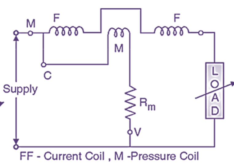
(c) Circuit diagram.
(b) Schematic Diagram
(e) Wattmeter box
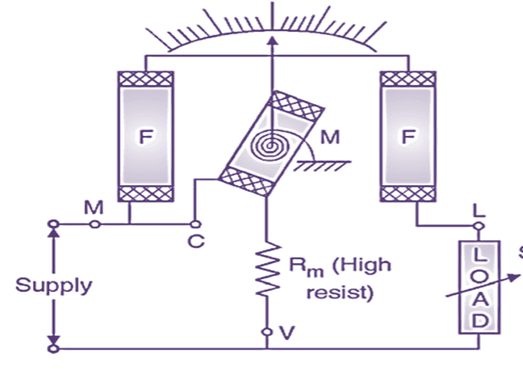
Fig. 1 : Electrodynamometer type wattmeter.
These are similar in construction and design as dynamometer ammeter and voltmeter the only difference is in connections of the two coils.
Working principle of Electrodynamometer type wattmeter
Interaction of magnetic flux between two coils produces a force on moving coil.
Construction of Electrodynamometer type wattmeter
The constructional details are shown in Fig. 1 (a). There are two coils, current coil or fixed coil (F) and voltage coil or moving coil (M). The fixed coil carriers the current of the circuit. This coil is divided into two halves (F, F). The fixed coil is wound with heavy wire and it is stranded to avoid eddy current loss in conductors. The fixed coil is designated as current coil. It’s two terminals are taken out as M and L on the meter.
The fixed coil carriers the current of the circuit. This coil is divided into two halves (F, F). The fixed coil is wound with heavy wire and it is stranded to avoid eddy current loss in conductors. The fixed coil is designated as current coil. It’s two terminals are taken out as M and L on the meter. The moving (M) coil is mounted on pivoted spindle and it is placed between the two halves of fixed coil. The moving coil is connected in parallel to the supply and it carries current proportional to the supply voltage.
Both fixed and moving coil are just wound as normal coils i.e. these are not wound on cores. The spring serves as incoming and outgoing leads for current or supply for moving coil. The current carried by this coil should not be too high because it may cause overheating of springs.
So to limit this current to safe value (below 100 mA) a high multiplier resistance (Rm) is connected in series with this moving coil as shown. The moving coil is designated as pressure coil. Its two terminals are taken out as C and V on the meter.
Deflecting torque is produced due to interaction of fixed coil flux and moving coil flux. The controlling torque is provided with the help of springs. The damping torque is provided by air friction damping arrangement (not shown in Fig. 1). Eddy current damping is not employed because the operating magnetic field is very weak which may be distorted due to eddy currents. Both fixed and moving coils are air cored. The constructional details can be summarised by following Table 1.
Working of Electrodynamometer type wattmeter
The connection of wattmeter is made as shown in Fig. 1(c). Both current coil and pressure coil carries current and produce their own magnetic flux.
Current coil flux ∝ Current coil current
Pressure coil flux ∝ Pressure coil current
∝ Supply voltage or load voltage
The interaction of two fluxes produces a torque on moving coil (M) i.e. pressure coil. The coil deflects and the deflection is proportional to power consumed by the load.
Advantages of Electrodynamometer Type Wattmeter
- It is free from Hysteresis and Eddy current losses
- Without modification it can be used for AC and DC.
- Highly accurate.
- Both active and reactive power can be measured by different.
Disadvantages of Electrodynamometer Type Wattmeter
- Cost is more.
- As iron core is not used magnetic flux is weak so more numbers of turns are required to produce desired magnetic field.
- Torque to weight ratio is small.
- Operate on weak magnetic field due to cores not used.
- It needs magnetic shielding.
Necessity of Range Extension of Wattmeter
C.T. and P.T. are used to extend the range of wattmeter. In practice, the range of quantity to be measured varies over a wide band i.e. power to be measured can be from small value (Milliwatt) to large value (Megawatt). The low range wattmeter current coil and pressure coil are not capable of handling large value of current and voltage. Hence their range is to be extended by some method.
Method of range extension of Wattmeter
CT (Current transformer) and PT (Potential transformer) is used to extend the range of wattmeter. Current coil of wattmeter is connected to the secondary of CT. Pressure coil of wattmeter is connected across secondary of PT. CT and PT step down current and voltage to a safe value hence low range wattmeter can be connected to measure high power. The connections are made as shown in Fig. 3.
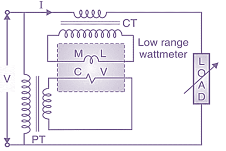
Fig. 3: Range extension of wattmeter by CT and PT.
A low range wattmeter is connected to CT and PT as shown in Fig. 3. The CT and PT ratio is known.
Actual power = Wattmeter reading × CT ratio × PT ratio
Comparison between current coil (cc) and pressure coil (pc) in Wattmeter
A wattmeter is an instrument, that reads power consumed in a circuit. The power is equal to the product of voltage across and current through the circuit therefore dc power (voltage × current) can be measured by connecting voltmeter and ammeter in a circuit as shown in the Fig 1. However, in an ac circuit, the power factor of the load also be taken into consideration.
Therefore, the ammeter and voltmeter in the above circuit can be replaced by a single instrument “wattmeter” (WM) which will read dc as well as ac power.
Fig. 4.1. Measurement of Power.
Types of Wattmeters
The wattmeters are of following types.
(l) Dynamometer wattmeters.
(a) Suspended coil torsion head type.
(b) Pivoted coil, direct indicating.
(2) Induction wattmeters.
(3) Electrostatic wattmeters.
(4) Thermal wattmeters.