An AC Voltage Controller consists of two SCRs connected in anti-parallel. Here power flow is controlled during both half-cycles positive as well as negative half-cycle therefore, it is called as single-phase full wave voltage controller or bidirectional voltage controller. Fig. 1 (a) shows the typical circuit of single-phase full-wave voltage controller with R load.
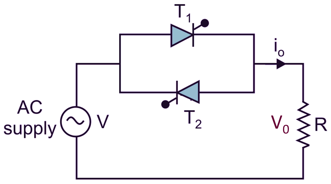
(a) Circuit diagram.
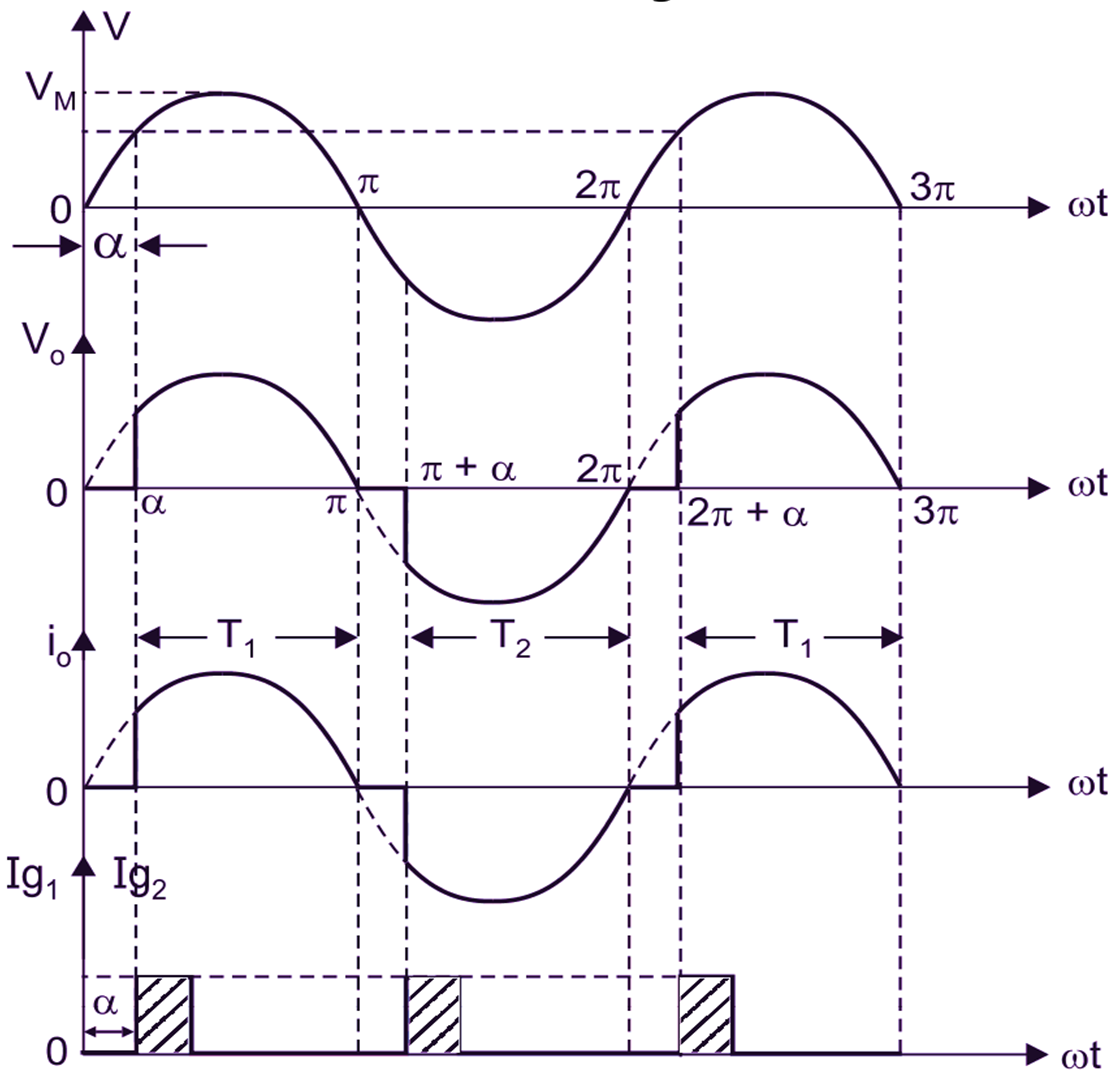
(b) Waveforms.
Fig. 1: Single-phase full-wave AC voltage controller with R-load
Working of AC Voltage Controller
During positive half-cycle of AC Input voltage, the anode of thyristor T1 is more positive with respect to cathode. T1 is fired at ωt = α therefore, the load is directly connected to supply (load voltage and supply voltage will be same). i.e.
V0 = V
From α to π. At ωt = π, the supply voltage goes through, natural reversal of supply voltage appears across thyristor T1, there it will be commutation at ωt = π.
During negative half-cycle of AC Input voltage, the anode of thyristor T2 is more positive than cathode, T2 is fired at ωt = π + α, therefore T2 conducts from (π + α) to 2π. At ωt = 2π the supply goes through zero. Therefore, natural commutation of T2 takes place at ωt = 2π. In Fig. 1 the gating circuits for T1 and T2 must be isolated. The firing angles of T1 and T2 are kept 180° apart there is no restriction on the values of firing angles α. Firing angle can be controlled from 0 to π and rms output voltage from V to 0. The waveforms for the input voltage, output voltage and gating signal for T1 and T2 are shown in Fig. 1 (b).
Mathematical Analysis of AC Voltage Controller
Expression of Average Output Voltage (Vavg):
The average value of the load voltage is given by,
\[{{V}_{avg}}=\frac{{{V}_{M}}}{\pi }\left[ 1+\cos \alpha \right]\]
Expression of RMS Output Voltage (Vrms):
The RMS value of the load voltage is given by,
\[{{V}_{rms}}=V{{\left[ \frac{1}{\pi }\left( \pi -\alpha +\frac{\sin 2\alpha }{2} \right) \right]}^{1/2}}\]
Expression of RMS Output Current (Irms):
The RMS value of the load current is given by,
\[{{I}_{rms}}=\frac{{{V}_{rms}}}{R}\]
\[{{I}_{rms}}=\frac{V}{R}{{\left[ \frac{1}{\pi }\left( \pi -\alpha +\frac{\sin 2\alpha }{2} \right) \right]}^{1/2}}\]
Advantages of AC Voltage Controller
- Power flow can be controller during both half cycles of AC Input voltage.
- The load voltage and load current waveforms are same. Hence, there is no DC component.
- Saturation problem of transformer and induction motors are eliminated.
Disadvantages of AC Voltage Controller
- Two SCRs are used in anti parallel, so triggering circuit required for is to be somewhat difficult.
- Instead of using TRIAC, the circuit using two SCRs, becomes complex and expensive.
Applications of AC Voltage Controller
- To control the intensity of light circuit
- Various controls likes speed control of motors, fan and heater control etc.