After reading the MATLAB Simulink topic, you will know how to create a new Simulink model in MATLAB, and you will also understand how to take full advantages of given Simulink library browser for your application using MATLAB.
It is a graphical, mouse-driven program that allows modeling of various systems and their analysis. For modeling a system, various blocks along with graphical user interface (GUI) provided by Simulink. Using Simulink, you create a system simply by placing blocks and connect them using wires and also analyze the system.
Simulink Library Browser
To open the Simulink Library Browser, you can use any one of the option discussed below:·
- By clicking the Simulink Library button,
 from the MATLAB default window as shown below
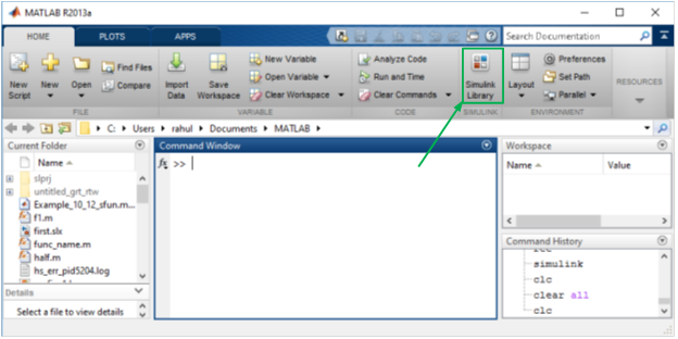
- By typing Simulink on the command window.
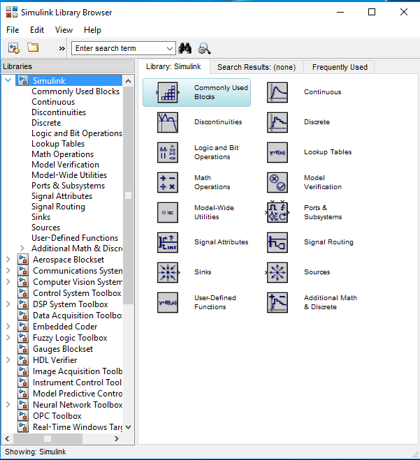
Using any one of the above-mentioned options, Simulink library browser window will pop up as shown below
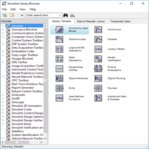
On the left side of the Simulink library browser, various libraries like Simulink, Aerospace Blockset, etc. will be seen.
Simulink
By clicking on the > sign next to Simulink, various categories as Commonly Used Blocks, Continuous, etc. will be displayed as shown below.
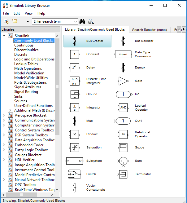
Each categories having different blocks. When we click on Commonly Used Blocks then different blocks appear like Bus creator, Constant, etc. as shown below:
Creating a New Simulink Model
First, you open a new model.
Opening a New Model
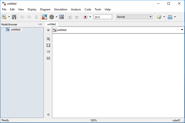
Once Simulink Library Browser window is opened, click on the New Model icon ![]() , from the toolbar of Simulink Library Browser. A New Model window will appear on the screen as shown below:
, from the toolbar of Simulink Library Browser. A New Model window will appear on the screen as shown below:
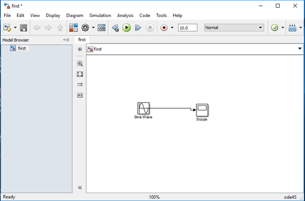
Now click on Simulink appear on Simulink Library Browser. On clicking Sources, a set of blocks will appear. Now drag and drop the Sine Wave to the model window.
Add new block, Scope from Sink appears in Simulink.
To save a model click on the floppy diskette icon ![]() , and let us save with file(model) name as first, a default file extension .slx, save the model as first.slx is shown below.
, and let us save with file(model) name as first, a default file extension .slx, save the model as first.slx is shown below.

To make the connection between blocks Sine Wave and Scope, place the cursor over the output port (represented as > sign) of Sine Wave block, as a sign + will appear, hold the left mouse key and drag from Sine Wave block to input port (represented as > sign) of Scope block. The black line connection appears between two blocks indicate no error in connection. The complete model is shown below:
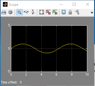
Running Simulation
By clicking on the play button ![]() icon.
icon.
To see Simulation result, double-clicking on the Scope block, a new Scope window will appear as shown below: