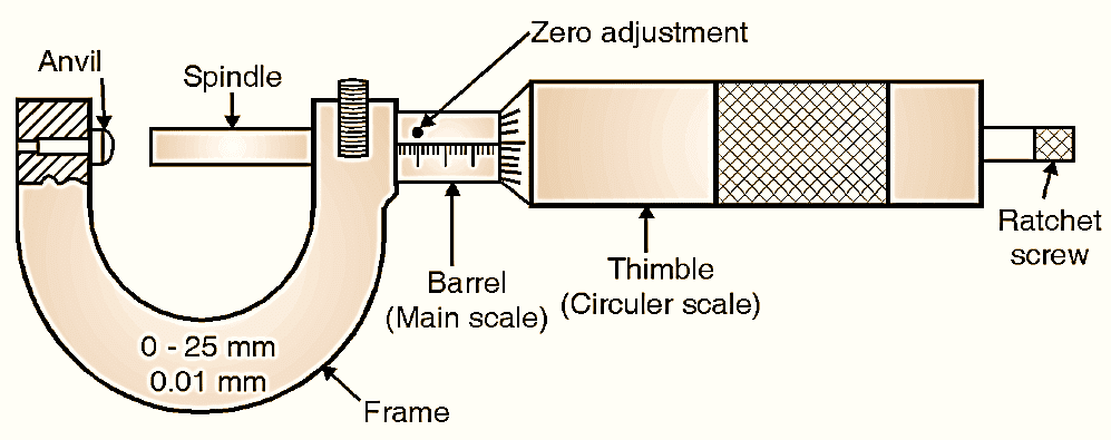
Figure 1: Micrometer.
Micrometer screw gauge works on the principle of nut and bolt. It consists of an accurate screw with about 10 or 20 threads per cm and revolves in a fixed nut. The rotation of thread is measured, which is already calibrated. In metric micrometers, the pitch of the screw is 0.5 mm so that one rotation of screw moves it axially by 0.5 mm. If main scale on barrel has least count of 0.5 mm.
\[\text{Least count = }\frac{\text{Smallest division on main scale}}{\text{Total number of division on circular scale}}\]
i.e.,
\[\text{LC = }\frac{0.5}{50}=0.01\text{ mm}\]
Micrometers can have least count of 0.01 mm, 0.001 mm, etc as per requirement and manufacturer.
Reading Micrometer (Least Count)
Four different cases are explained below to know reading micrometer.
Total Reading = (Main scale reading) + (Circular scale division) × (Least count)
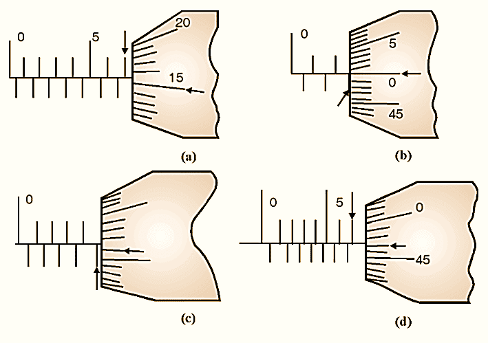
Figure 2.
Case (a):
Find MSR i.e. number of divisions visible on the main scale. Find number of divisions crossed on circular scale by the horizontal line on main scale (Reference line), that is CSD. Refer to Fig. 2(a),
TR = MSR + CSD × LC
= 7 + 15 × 0.01 = 7.15 mm
Case (b):
Refer to Fig. 2(b)
TR = MSR + CSD × LC
= 2.5 + 0 × 0.01 = 2.5 mm
Case (c):
Refer to Fig. 2(c)
TR = MSR + CSD × LC
= 4.5 + 1 × 0.01 = 4.51 mm
Case (d):
Refer to Fig. 2(d)
TR = MSR + CSD × LC
= 7 + 47 × 0.01 = 7.47 mm
Construction and Working of Simple micrometer
Simple micrometer consists of a screw with fixed pitch and nut arrangement. The end of screw acts as a spindle / anvil in the base of the frame. Spindle can be advanced or retracted by using thimble connected to spindle. The barrel has engraved lines of main scale (LC = 0.5 mm) which is true scale. Thimble has circular scale with number of divisions engraved on it. A lock nut is provided for locking a dimension. (Fig. 1). The Ratchet screw provides a stop, if excessive pressure is applied by the anvils, which is one of the most important part for avoiding errors. When two jaws touches each other, zero reading is expected. If it is not observed, error can be adjusted by rotating barrel itself. Fig. 3 shows a digital micrometer.
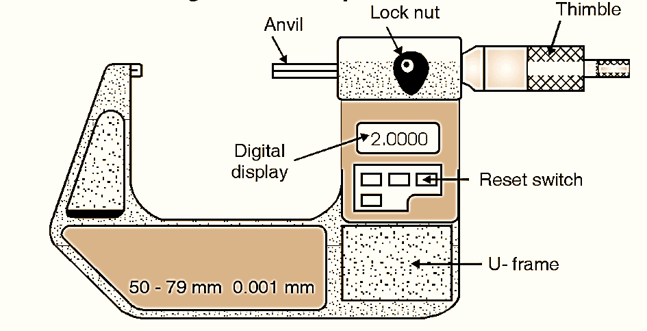
Figure 4: Digital Micrometer.
Depth Micrometer
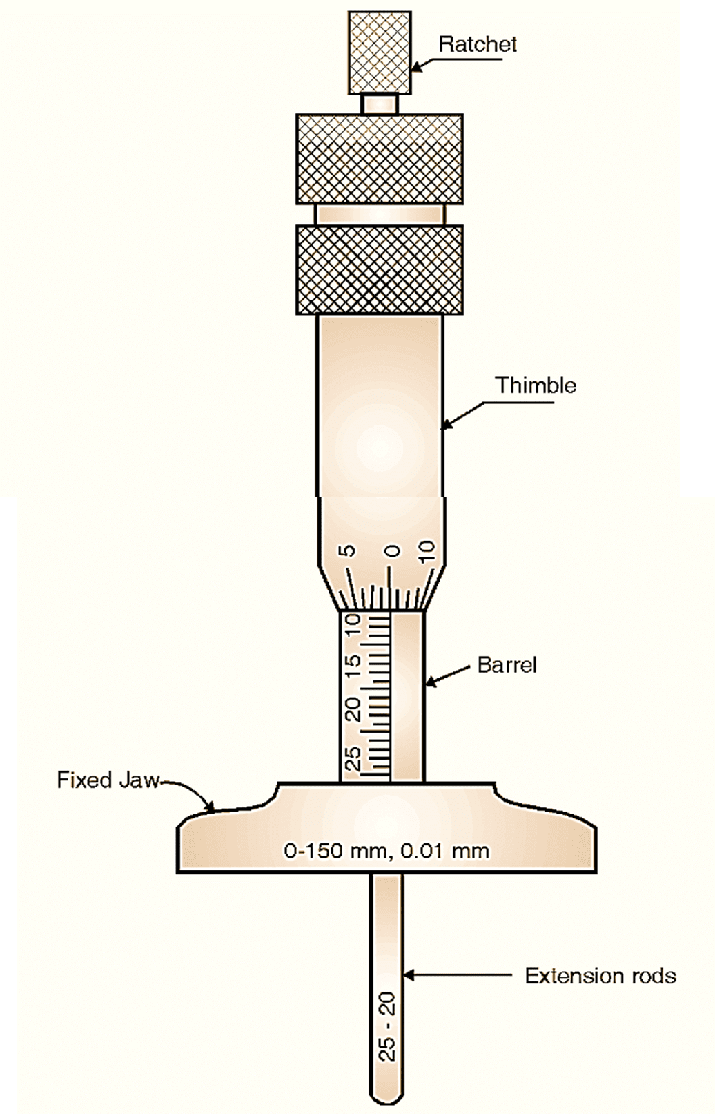
Figure 4: Depth Micrometer.
Depth micrometer is used for measuring depths of holes, slots, etc. Its principle is similar to micrometer. It consists of one shoulder that acts as the reference while measurement is carried out. Extension rods can be used for large ranges of measurement e.g.
Rod-1: Range 0 – 25
Rod-2: Range 25 – 50
Rod-3: Range 50 – 75
Rod-4: Range 75 – 100
If extension rods are used, the reading is to be calculated as :
Total Reading = [MSR + (CSD × LC)] + [Lower range of extension rod.]
A very important point to be noted is that its scale is calibrated in the reverse direction. Refer to Fig. 4.
Inside Micrometer
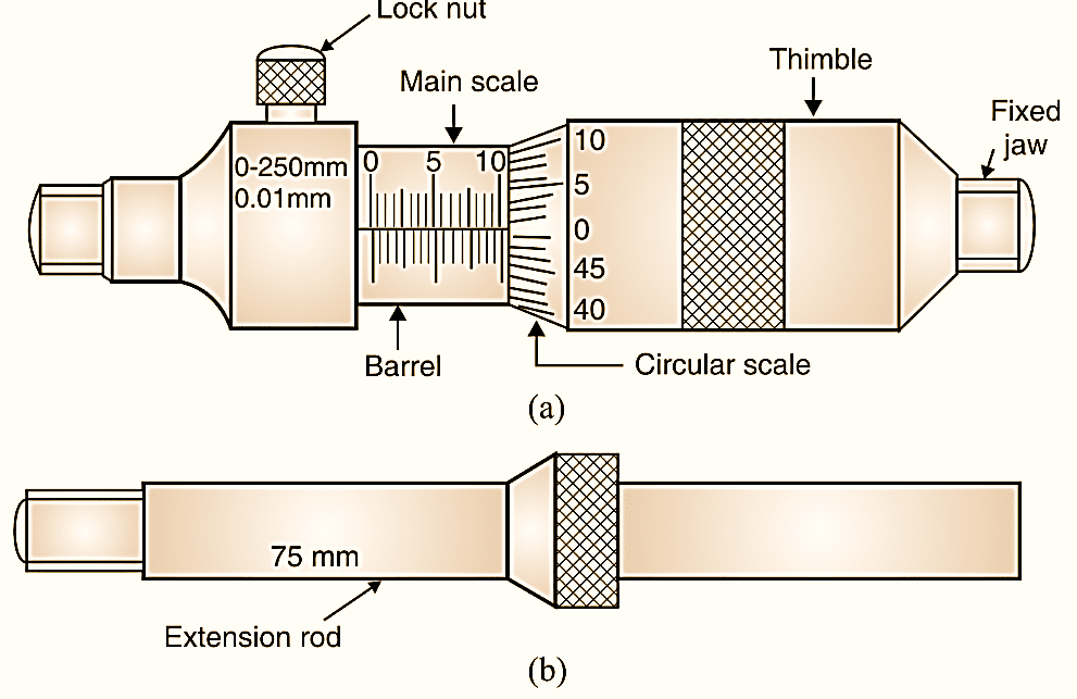
Figure 5: Inside Micrometer.
Fig. 5 shows inside micrometer with micrometer unit, extension rods, spacing collars, etc. The basic micrometer consists of a nut bolt principle and range starting from 50 onwards or like that. For various inner dimensions, extension rods can be attached as per the requirements. Number of extension rods can be attached at a time and larger distance can be measured e.g. Minimum 175 i.e. [Basic unit (50) + Extension rod (25) + Extension rod (100)] to maximum 188 (i.e. 175 + 13).
Collar is provided for avoiding errors in the readings provided on extension rods. Zero error can be adjusted by using master unit provided with instrument.
Precautions While Using Micrometer
- Instruments must be used by proper process.
- It must be calibrated.
- It is to be used with standard environmental conditions.
- Vibrations or such errors are to be avoided.
- Proper knowledge is needed about method of reading an instrument.
- Proper least count range is to be selected.