In this topic, you study the Series combination of resistances with neat sketch.
The resistances are connected in such a way as to form a single path for the current. The end of first resistance is connected with the start of second and end of second with the start of third resistance, thus these connections are known as series connections as shown in Fig. 1.
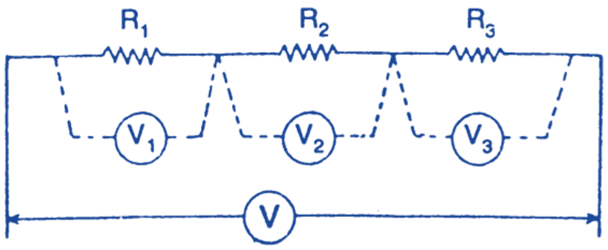
Fig. 1. Series circuit
The circuit has got the following characteristics:
(0 There is only one path Of the Current to flow, hence same current will flow through all resistances.
(ii) The current drawn is equal to the
Voltage (V)
Equivalent resistance (Req)
hence if at a given voltage more resistances are added in series the current will decrease.
(iii) The voltage drop across individual resistance depends upon the value of current and its resistance, as shown in Fig. 7.7.
(iv) The sum of the voltage drops across each resistance is equal to the applied voltage, i.e.
(v) Substituting for individual values in the above equation
V -1. RI +1.R2+1.R3
– I(RI + R2+ R3)
Let the circuit has an equivalent resistance as R Now the voltage is consumed by the entire circuit so,
I(RI + R3)
RI +R2+R3 …Q
Hence when a number Of resistances are connected in series, the total resistance is equal to the sum of individual resistances.
Uses. (i) The series circuits are used for decoration lightings.
(ii) This circuit is also used for voltage drop purposes.
(iii) It is also used for series testing purposes.