In this topic, you study the Parallel combination of resistances with neat sketch.
The circuit in which the beginning of all resistances are connected to one terminal and the ending terminals to another terminal, is known as the parallel circuit as shown in Fig. 1. In this circuit the branch currents are different depending upon the individual branch resistances.
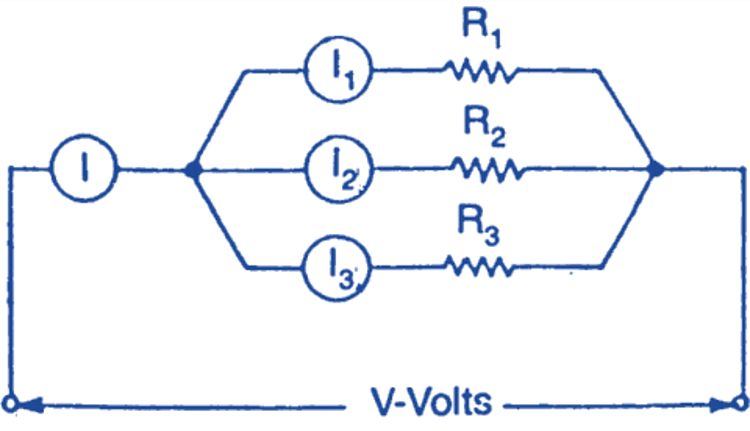
Fig. 1. Parallel circuit.
This circuit has got the following characteristics:
- The voltage across each resistance is same.
- There are as many branch currents, as many number of branches.
- The branch currents can be calculated as the branch current
- The sum of the branch currents is equal to the Current drawn from the mains.
- The equivalent or total resistance can be calculated as
Let Req be the equivalent resistance of the circuit. Now substituting for the currents
Hence in parallel combination, the reciprocal Of the equivalent resistance is equal to the sum of reciprocals of different branch resistances.
Conductance
In parallel circuit the conductance increases with the addition of the further resistances in the parallel.
Application
It is applicable in house (domestic) and factories (industrial) wiring for connecting different appliances. Obviously all lamps, fan, kettle, motor, etc. are connected in parallel.
Note
When the equal values of resistance are connected in parallel, the equivalent resistance of the combination will be equal to the branch resistance divided by the number of branches.