A direction control valve which has ability of infinite positioning and regulates the flow quantity, speed of motor is called servo valve. Mostly hydro electric servo systems employ servo valves for higher efficiency, response time and compactness. These valves are connected to feedback sensors to control the actuator’s position, velocity and acceleration very precisely.
Types of Servo Valve
It is classified into two types.
- Electro hydraulic servo valve.
- Mechanical hydraulic servo valve.
Electro hydraulic servo valve
Electro hydraulic Servo valves can be single stage or multistage, where the movement of valve spool is proportional to the input electric signal. The figure 1 below shows the multistage hydro electric servo valve which mainly consists of torque motor, double nozzle and a spool.
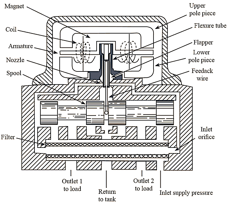
Figure 1: Electro hydraulic servo valve.
Construction of Electro hydraulic Servo valve
In the electric torque motor. the two coils are winded over the armature and the magnets are arranged below and above it. The flexure tube is used to prevent the fluid flow into the electromagnetic field. Flapper is connected at the armature centre and extended down to the nozzle area through flexure tube. Two nozzles are provided on either side of flapper and corresponding inlet orifices are provide at the ends of filter as shown in figure 1. The feedback wire is connected to the spool and armature such that the spool displacement can be controlled based on the required flow rate.
Working of Electro hydraulic Servo valve
The pressurized fluid is passed through the filter and supplied to the nozzles by any one of the inlet orifice. The clockwise or anticlockwise torque developed on the armature due to electric current causes the flapper displacement between the nozzles. The nozzles openings are varied by the motion of flapper. Thus, the variation in flapper motion produces pressure difference between two ends of spool which causes the spool displacement either to left or right direction. The fluid flows to the outlet load sections with required pressure and quantity, as directed by the spool movement. The feedback wire which is connected to the spool applies reverse torque (counter clockwise or clockwise) on the armature and flapper returns to its centre position. Thus, the spool remains in its position for the next input electrical signal.
Applications of Electro hydraulic Servo valve
The hydro electric servo valves are used in following various industrial and automobile applications
- Farm machinery
- Cargo handling cranes
- Earth moving vehicles
- Logging equipment
- Fire and lift trucks.
- Vehicle servicing equipment.
- Pivoted arm devices.
- Steel mill industrial control etc.
Mechanical Hydraulic Servo Valve
Mechanical-Hydraulic Servo Valve: In this type of servo valve, the required amount of force is applied to valve spool through force amplifier such that the spool movement opens the port A and shuts the port B. The fluid from the tank flows into the hydraulic cylinder through port A and pushes the piston towards right as shown in figure 2. The feedback link is arranged such that, it forces the sliding sleeve in right side direction to restrict the flow to the cylinder. Due to this, the desired amount of output motion is obtained for a given input force. It is a closed loop system and is used in automobiles hydraulic power steering system.
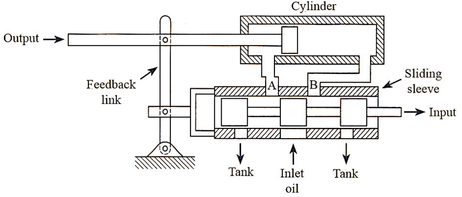
Figure 1: Mechanical hydraulic servo valve.