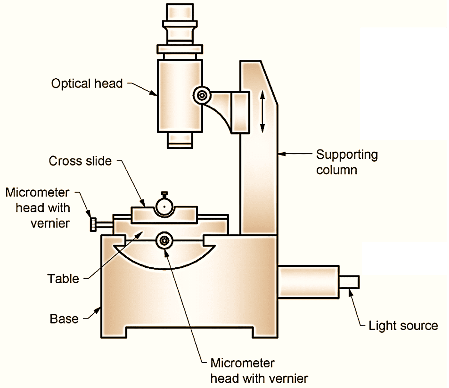
Figure 1: Tool Maker’s Microscope.
Tool Maker’s Microscope is a direct reading measuring instrument used extensively in the shop for inspecting gauges, tools, screw threads, jigs, dies, and fixtures. The essential features of the microscope are shown in Fig. 1.
Construction and Working of Tool Maker’s Microscope
The workpiece to be inspected is mounted on a micrometer stage under a microscope. The stage is operated by two accurate micrometer screws on compact slides moving on precision ball bearings.
The movement of the slide can be measured to 0.0002 mm in the horizontal plane in two mutually perpendicular directions. The microscope provides a magnification of 10 to 100 times. The dimension is measured by first aligning the microscope hairlines at one end of the dimension to be measured and then moving the table till the other end of the dimension reaches the hairline.
The movement of the table as read by the micrometer is the length of the dimension. A protractor ocular with two angular scales is provided with the tool maker’s microscope for angular measurements. This can be used for measurement of angles with a least count of 1 minute. To make an angle measurement the eye piece hair line is first made parallel to one side of the angle being measured and the reading on the protractor scale noted. The hairline is then rotated to touch on the other side of the angle and the angle is read again. The difference in the two readings is the angular measurement desired. When making measurements on screw threads, worms, hobs, and other similar tools it is necessary that the microscope be tilted at an angle from the vertical. This adjustment is provided on the microscope with the help of two tangent screws.
A common tool maker’s microscope has a longitudinal range of 100 mm and a cross range of 50 mm. 50 mm of the longitudinal movement are obtained by the screw while the remaining 50 mm are obtained by insertion of gauge blocks.