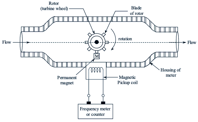
Figure 1: Turbine Flow Meter.
Working Principle of Turbine Flow Meter
The permanent magnet attached to the body of rotor is polarized at 90° to the axis of rotation. When the rotor rotates due to the velocity of the fluid (V) the permanent magnet also rotates along with the rotor. Therefore a rotating magnetic field will be generated. which is then cut by the pick-up coil. Due to this A.C. voltage pulses are generated whose frequency is directly proportional to the flow rate.
Measuring range: Accurate flow measurement overa wide flow range = 0.1 to 50,000 gallons/mm. Sizes = 6.35 mm to 60 mm.
Construction and Working of Turbine Flow Meter
This flow meter consists of a rotor pivoted along the axis of the pipe and it is designed in such a way that rate of rotation of rotor is proportional to the rate of flow of liquid through the pipe. Refer Fig. 2. The rotor consists of small permanent magnets. When rotor rotates, this magnetic field also rotates, so it is a rotating magnetic field. There is a coil fitted at the surface of pipe. The coil is stationary and the magnetic field is rotating. So flux linking with the coil changes and an e.m.f. is induced in the coil. The amount of e.m.f. induced depends upon flow rate. Thus, electrical voltage proportional to flow rate is obtained.
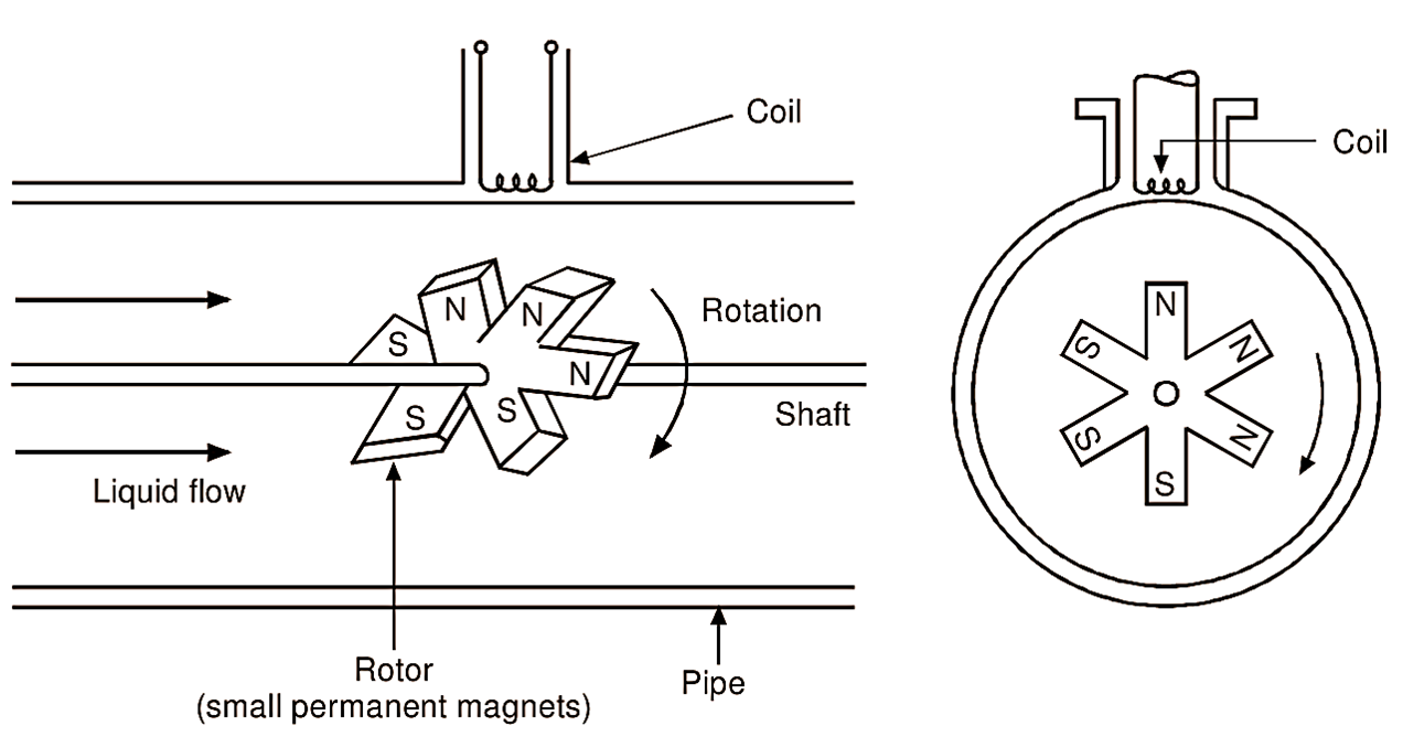
Figure 2: Working of Turbine Flow Meter.
The turbine flow meter contains a hydraulically supported turbine rotor to which a permanent magnet (polarized at 90° to the axis of rotation) is joined (Figure 1). This assembly is placed inside the pipeline whose volume flow rate it to be determined. A pick-up coil is located on the outside of the meter housing and the output terminals of the pick-up coil are connected to the counter or frequency meter.
When the fluid flows through the pipe line it strikes the rotor. Therefore, the rotor along with the permanent magnet rotates. Due to this a rotating magnetic field is generated. During rotation, when the magnet passes the pick-tip coil, the coil cuts the magnetic field and generates an A.C. voltage pulse. As the rotor rotates continuously a series of voltage pulses will be generated and fed to the frequency meter or counter which totalizes pulses and indicates the frequency. This indicated frequency gives the measure of fluid flow rate (when calibrated). From the displayed output (total number of pulses) the volume flow rate can be calculated using the formula,
\[\text{Q}=\text{ }\frac{\text{F}}{\text{C}}\]
where,
Q = Volume flow rate
F = Total number of pulses
C = Flow coefficient.
Advantages of Turbine Flow Meter
- Electrical output is available.
- Recording and controlling of flow is possible from remote location.
- Accuracy is high and also provides good dynamic response.
- Installation and maintenance is easy.
- Less pressure drop in the fluid.
Disadvantages of Turbine Flow Meter
- The bearing of the rotor may be subjected to corrosion.
- There is a problem of external frictional torques and wear-tear.
Applications of Turbine Flow Meter
- These are used to determine the fluid flow in pipes and tubes.
- This can be applied to know the flow of water in streams and also in rivers.
- This can be used to determine the wind velocity in weather solutions.