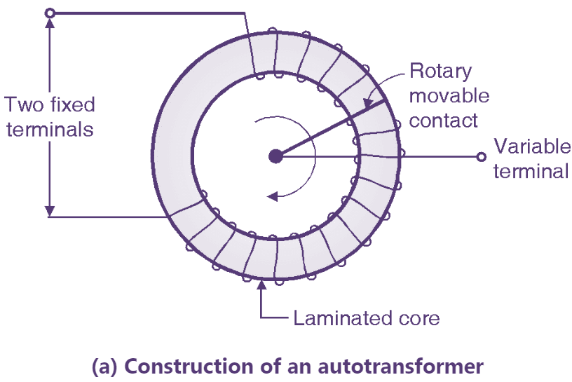
Fig. 1: Autotransformer (Construction & Symbol).
The normal transformer has separate primary and secondary windings. But the autotransformer is a special transformer in which a part of winding is common for the primary and secondary windings. The construction of an autotransformer is as shown in Fig. 1. It consists of only one winding wound on a laminated magnetic core, with a rotary movable contact. Thus from the autotransformer three terminals are brought out for connection. The autotransformer can operate as a step down or a step up transformer.
Autotransformer as Step Down Transformer
Connection diagram
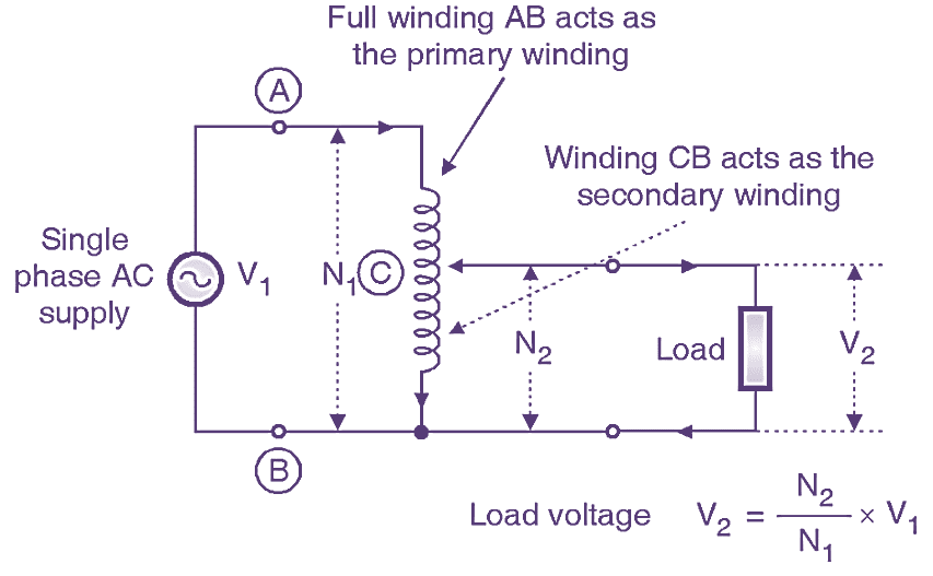
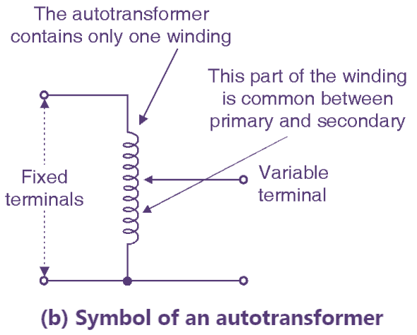
Fig. 2: Step-down autotransformer
The connection of autotransformer as a step down transformer is shown in Fig. 2. It shows that the two fixed terminals A and B are connected to the single-phase AC supply V1. Thus winding AB acts as the primary winding. A part of the complete winding i.e. CB acts as the secondary winding across which the load is connected. The operating principle of an autotransformer is same as that of the normal transformer. Therefore the load voltage for this configuration is given by,
\[{{V}_{2}}=\frac{{{N}_{2}}}{{{N}_{1}}}\times {{V}_{1}}\]
Where,
N2 = Number of turns corresponding to secondary i.e. CB
N1 = Number of turns corresponding to primary i.e. AB.
As the number of turns corresponding to winding CB i.e. N2 is less than that of winding AB i.e. N2, this configuration operates as step down transformer. If we neglect the losses, the magnetizing current and the leakage reactances, then the transformation ratio is defined as,
\[K=\frac{{{V}_{2}}}{{{V}_{1}}}=\frac{{{N}_{2}}}{{{N}_{1}}}=\frac{{{I}_{2}}}{{{I}_{1}}}\]
Where,
I2 = Primary current
I1 = Load current.
Autotransformer as a Step Up Transformer
Connection diagram
Fig. 3: Step-up autotransformer
Fig. 3 shows the connection of an autotransformer for operating it as the step up transformer. Note that the part C3 of the complete winding acts as the primary winding. The ac input voltage VI is applied between terminals C and B. The full winding AB acts as a secondary winding and the load is connected between these terminals. As the number of turns of winding AB (now N2) is higher than the number of turns of winding CB (now N2) the autotransformer now acts as a step up transformer. Neglecting the losses, the magnetizing current and the leakage reactances, the load voltage V2 is given by,
\[{{V}_{2}}=\frac{{{N}_{2}}}{{{N}_{1}}}\times {{V}_{1}}\]
Copper Saving in Autotransformer
The cross sectional area of a wire is decided by the value of current flowing through it. Larger the area, smaller is the resistance and higher is the current carrying capacity.
Area ∝ I
The length of the wire is proportional to the number of turns.
Length l ∝ N
The weight of copper required is proportional to area and length.
\[\text{Weight of copper }\propto \text{ Area }\times \text{ Length}\]
But Area ∝ I and l ∝ N
Thus,
\[\text{Weight of copper }\propto \text{ NI}\]
Weight of copper in a two winding transformer
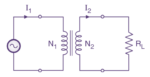
Fig. 4: Two winding transformer
Consider a two winding transformer of Fig. 4. Let the total weight of copper be Wc.
\[{{W}_{C}}={{W}_{1}}+{{W}_{2}}\]
Where W1 is the weight of copper for primary and ‘W2’ is the weight of copper for secondary.
But W1 ∝ N1 I1 and W2 ∝ N2I2.
Total weight of copper WC ∝ (N1I1 + N2I2)…(1)
Weight of copper in a step down autotransformer
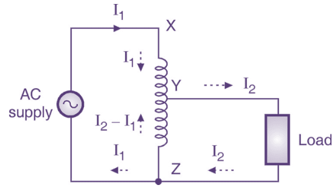
Fig. 5: Step down autotransformer
Consider the step down autotransformer of Fig. 5.
Number of turns
\[XZ={{N}_{1}}\]
\[YZ={{N}_{2}}\]
\[XY={{N}_{1}}+{{N}_{2}}\]
Weight of copper of section XY ∝ (N1 – N2)I2
\[\text{ }\propto \text{ (}{{\text{N}}_{1}}\text{-}{{\text{N}}_{2}}\text{)}{{\text{I}}_{2}}\]
Weight of copper of section YZ ∝ N2(I2 – I1)
\[\text{ }\propto \text{ }{{\text{N}}_{2}}\text{(}{{\text{N}}_{2}}\text{-}{{\text{N}}_{1}}\text{)}\]
Hence the total weight of copper is given by
\[\text{ }{{W}_{A}}\propto \left[ \left( {{N}_{1}}-{{N}_{2}} \right){{I}_{2}}+{{N}_{2}}\left( {{I}_{2}}-{{I}_{1}} \right) \right]…(2)\]
Saving of copper
Take the ratio of Equations (1) and (2) to get
\[\frac{{{W}_{c}}}{{{W}_{A}}}=\frac{{{N}_{1}}{{I}_{1}}+{{N}_{2}}{{I}_{2}}}{\left( {{N}_{1}}-{{N}_{2}} \right){{I}_{1}}+{{N}_{2}}({{I}_{2}}-{{I}_{1}})}…(3)\]
But, \[K=\frac{{{N}_{2}}}{{{N}_{1}}}=\frac{{{I}_{1}}}{{{I}_{2}}}\]
I2 = I2/K and N2 = KN2. Substituting in Equation (3) we get,
\[\frac{{{W}_{c}}}{{{W}_{A}}}=\frac{{{N}_{1}}{{I}_{1}}+K{{N}_{1}}({{I}_{2}}/K)}{({{N}_{1}}-K{{N}_{1}}){{I}_{1}}+K{{N}_{1}}({{I}_{2}}/K-{{I}_{1}})}\]
\[=\frac{2{{N}_{1}}{{I}_{1}}}{{{N}_{1}}{{I}_{1}}-K{{N}_{1}}{{I}_{1}}+{{N}_{1}}{{I}_{1}}-K{{N}_{1}}{{I}_{1}}}\]
\[=\frac{2{{N}_{1}}{{I}_{1}}}{2{{N}_{1}}{{I}_{1}}-2K{{N}_{1}}{{I}_{1}}}\]
\[=\frac{2{{N}_{1}}{{I}_{1}}}{2{{N}_{1}}{{I}_{1}}\left( 1-K \right)}\]
\[\frac{{{W}_{c}}}{{{W}_{A}}}=\frac{1}{\left( 1-K \right)}\] \[{{W}_{A}}=\left( 1-K \right){{W}_{c}}\]
This shows that the copper required for the autotransformer is less than that required for a two winding transformer.
\[\text{Saving of copper = }{{W}_{C}}-{{W}_{A}}\] \[={{W}_{C}}-\left( 1-K \right){{W}_{C}}\]
\[=K{{W}_{C}}\]
So the saving of copper for a step down autotransformer is K times the total copper weight of the two winding transformer. For a step up transformer we can prove that,
\[\text{Copper saving = }\frac{{{W}_{C}}}{K}\]
Advantages of an Autotransformer
- As only one winding is used, the copper required for the transformer is very less.
- The size and hence the cost is reduced as compared to the conventional transformer.
- The losses taking place in the winding are reduced hence the efficiency is higher than the conventional transformer.
- Due to reduced resistance, the voltage regulation is better than the conventional transformer.
Disadvantages of an Autotransformer
- There is no electrical isolation between the primary and secondary windings. This can prove to be dangerous for high voltage applications.
- If the common part of the winding (winding CB) breaks (open circuited) then the transformer action is lost and full primary voltage appears across the secondary.
- It possess a low impedance, hence if the secondary circuit is short circuited, then a large current will flow on the secondary side.
Applications of an Autotransformer
- It can be used as a variac, i.e. variable ac supply to vary the ac voltage applied to the load smoothly from 0 V to about 270 V.
- In order to start the ac machines such as induction motors or synchronous motors.
- To vary the supply voltage (as per requirements) of a furnace.
- When the variac autotransformer is used to control the intensity of lamps in the cinema halls etc., it is called as the dimmerstat.
Autotransformer as Dimmerstat
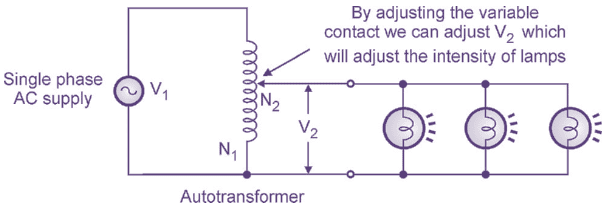
Fig. 6: Autotransformer as Dimmerstat.
When an autotransformer is used for the application of light dimming in the cinema halls or on the stage of play, it is called as dimmerstat. By varying the position of the variable contact, we can adjust the ac voltage applied to the lamps as shown in Fig. 6. The secondary voltage,
\[\text{}{{V}_{2}}=\frac{{{N}_{2}}}{{{N}_{1}}}\times {{V}_{1}}\]
With change in position of the variable contact the value of N2 changes. This will change the value of V2 and hence the intensity of lamps which are acting as load.