The phenomenon of lagging of magnetisation or induction density behind the magnetising force when a specimen of ferromagnetic material is taken through a cycle of magnetisation is known as the magnetic hysteresis.
BH Curve
The curve which shows the relationship between the magnetising force and magnetic flux density of a magnetic substance is known as the BH curve, where B – the flux density i.e. Φ/A and H – the magnetising force i.e. IN/l. Let the coil has N turns and l, the length which is constant in this particular case. So H ∝ I and the current shown by ammeter will itself indicate the magnetising force.
Let the specimen AB be an unmagnetised soft iron piece, which is wound as shown in Fig. 1. The magnetising force can be increased or decreased by increasing or decreasing the current through the wound solenoid (switch S in closed position). When current is zero the H is also zero and flux density initially is zero. As H i.e. current is increased the flux density also increases. The rate is higher at the staring time and the rate gradually decreases with the increasing of current. There is one stage when flux density does not increase even when the current is increased, that is known as the saturation point. Here both the flux density and the magnetising force are positive and if these are plotted the curve will be as shown in Fig. 2. The curve is known as BH curve.
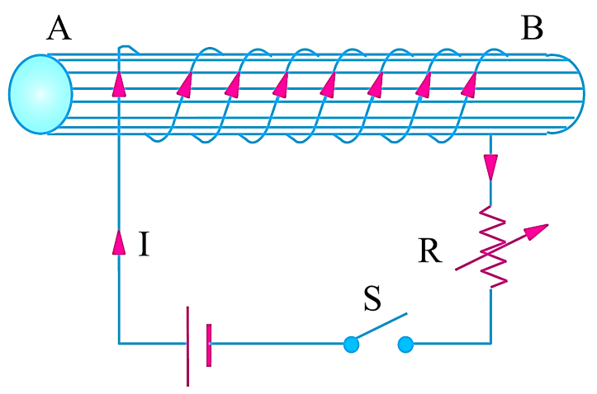
Fig. 1. Electrical circuit to draw B.H. Curve.
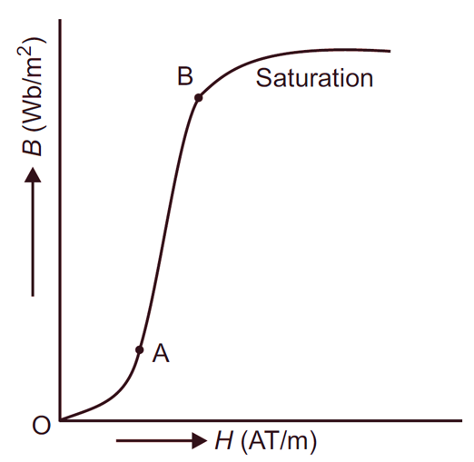
Fig. 2. BH Curve
Uses of BH Curve
- It is used to find out the saturation point Of the magnetic materials, so it is useful for designing purpose.
- It is used to find out the permeability i.e. B/H of the material.
Hysteresis loop
The specimen AB is subjected to the different magnetising force, more or less, positive or negative. Similarly the flux density s produced will also be effected and changed. Let the magnetising force H, here I, is increased in positive direction, then flux density B is also increased up to the saturation point. When gradually the magnetising force is decreased, the flux density does not follow the same curve and even if the magnetising force is zero, the flux density is not zero but follow ab as shown in Fig. 1. At ‘b‘ though the magnetising force is zero but ob is the magnetic flux density left behind the magnetising force and is known as the residual magnetism.
To demagnetise the specimen, the reversed magnetising force is to be used, which is ‘Oc‘ and is known as coercive force. Now if the current is further increased, the piece will be magnetised in the reversed order till the saturation. Again when the force is decreased the curve takes it new position as ‘de‘ and here Oe is the residual magnetism and of is the coercive force which is applied to demagnetise the residual magnetism. If this magnetising force is increased the curve finally comes to point ‘a’ making a closed loop ‘a, b, c, d, e, f, a‘ and this loop is known as the hysteresis loop.
In this loop ‘Ob‘ and ‘Oe‘ represent the residual magnetism and ‘Oc‘ and ‘Of‘ represent the coercive force. The hysteresis results due to the fact that the molecules of a magnetic material are not perfectly elastic, once arranged in an orderly fashion by the magnetising force, the molecules, molecular magnetic do not return exactly to their original position, when the magnetising force is removed, but retains some residual magnetism. This results in lagging of B behind the H and called magnetic hysteresis.
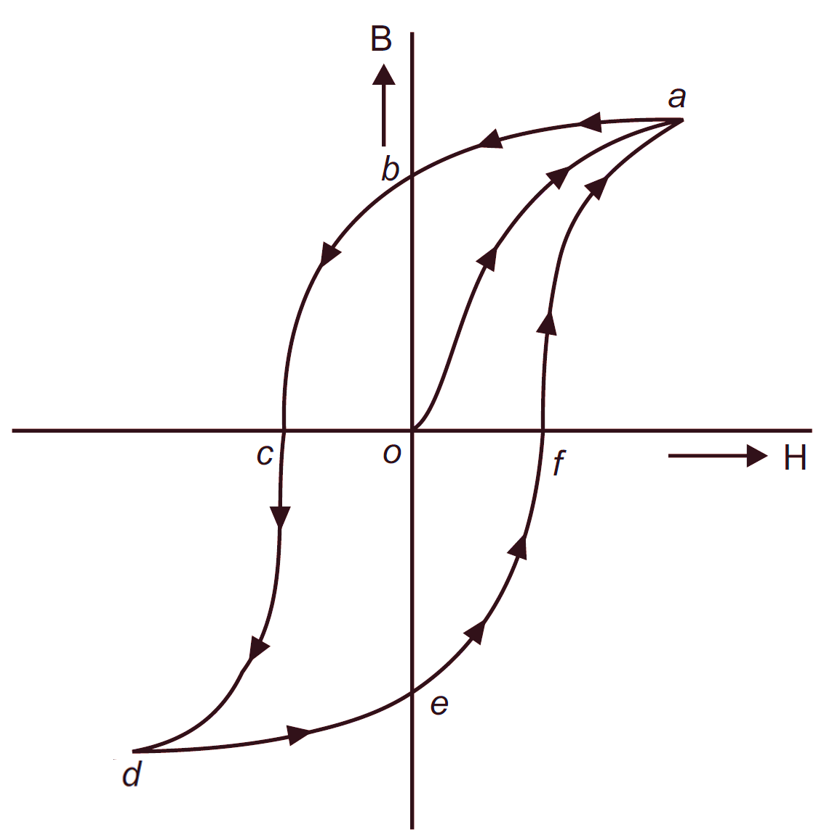
Fig. 3. Hysterøssis loop
Hysteresis loss
The coercive force does not perform any useful work. It is a kind of loss and is known as hysteresis loss. It produces heat. The hysteresis loss depends upon:
Area of the hysteresis loop: The larger the area of the loop greater will be the hysteresis loss.
Frequency of reversal of magnetisation: The loss is directly proportional to the frequency of reversal.
Volume of the material: Greater will be the volume of the material larger will be the hysteresis loss.
The flux density: This loss is directly proportional to the flux density ($\text{B}_{\text{m}}^{\text{1}\text{.6}}$).
Type of the material: It also depends upon the type of the material. Now the hysteresis loss can be given as
\[{{W}_{h}}=\eta \cdot B_{m}^{1.6}\cdot f\cdot V\text{ watts}\]
where Wh = Hysteresis loss in watts
η = Steinmitz constant or hysteresis constant
Bm = The maximum flux density in Wb/m2
f = Frequency
V = Volume of the material.
Effects of Hysteresis loss
It has the following effects:
- More hysteresis loss produces more heat.
- Loss of electrical energy is increased.
- As heat is increased so the insulation of the machine may be damaged or weakened.
The hysteresis loss cannot be avoided but can be minimised by adding some percentage of silicon in the iron.