Capacitive transducer works on the principle of change in capacitance. Capacitance changes, when there is,
- Change in overlapping area ‘A’ of plates.
- Change in distance ‘d’ between two plates.
- Change in dielectric constant ‘K’.
Construction of Capacitive Transducer
Capacitive transducer consists of two or more metal plate conductors separated by a dielectric medium or material, which acts as an insulator. The dielectric material may be air, mica, oil, paper etc. Fig. 1 shows capacitive transducer, where air is dielectric medium existing between two parallel metal plates. Value of dielectric constant (K) is different for different dielectric medium or material.
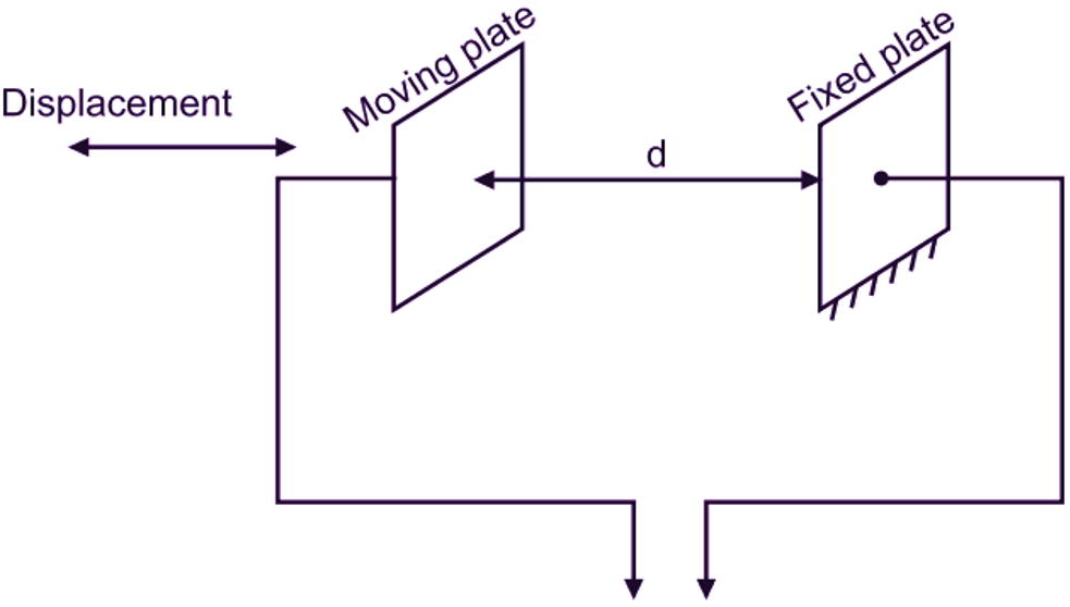
Fig. 1: Capacitive Transducer
Working of Capacitive Transducer
When voltage is applied across the plates, equal and opposite charges are generated on the plates. The capacitance of a parallel plate capacitor is given by the equation,
\[\text{C}=\frac{\text{KA}}{\text{d}}….(1)\]
where,
A = Area of each plate or Overlapping area of plates
d = Distance between two plates
K = Dielectric constant of medium existing between parallel
Thus, the capacitance ‘C’ can be changed by changing the dielectric medium (i.e. dielectric plates constant “K”) or changing the area of plates ‘A’ or changing distance ‘d’ between plates. This results into change in output voltage of circuitry. These changes can be caused by physical variables such as displacement, force, pressure. From Fig. 1, it can be observed that, one plate is fixed, whereas, second plate is capable to move. Also, it can be seen that, plates having same cross-sectional area are placed or located in such a way that, overlapping area of plates (A) will remain unchanged, if moving plate is moved towards or away from the fixed plate in horizontal direction. Similarly, dielectric medium, i.e. air will remain unchanged during horizontal displacement of moving plate. Therefore, value of delectric constant (K) will be constant. Therefore, equation (1) can be written as,
\[\text{C}\propto \frac{\text{1}}{\text{d}}\]
(since ‘A’ and ‘K’ are constant)
When moving plate is displaced horizontally leftwards or rightwards, value of capacitance (C) will change due to change in distance ‘d’ between the two plates, which can measured. For measurement, calibrated voltmeter is connected to output terminals of circuitry, which can be calibrated to give a direct reading of change in distance between two plates, i.e. displacement of moving plate. Change in capacitance can also be measured by an A.C. bridge, which gives the change in distance between two plates. Hence, linear displacement can be measured. Capacitive transducers are also used for measurement of angular displacement.
Advantages of Capacitive Transducer
- It requires very small force to operate, hence it can be used in small system also.
- Excellent frequency response.
- Extremely sensitive.
- Easy to fabricate.
- Require small power to operate.
- Simple in construction.
Disadvantages of Capacitive Transducer
- Non-linear behaviour.
- High output impedance.
- Poor frequency response.
Applications of Capacitive Transducer
- For measurement of both linear and angular displacements.
- For measurement of humidity in gases.
- For measurement of volume density, liquid level, weight, etc.