In this topic, you study Characteristics of DC Generators.
In general, for any machine, a performance characteristic means a graph between two related quantities one of which is considered as the independent variable. Following are the most important characteristics of a d.c. generator :
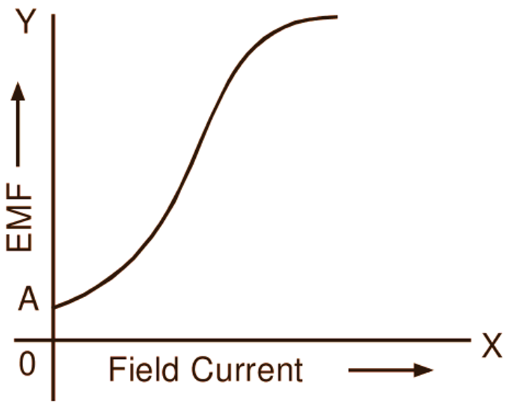
Open Circuit Characteristic (O.C.C.)
It is a graph between the emf generated (E) and the field current (If) at a given speed. Sometimes, this curve is also called the no-load characteristic or magnetization curve. When a particular machine is run at constant speed on no load, the induced emf is proportional to the flux per pole (Φ) and therefore to the flux density (B). Also the turns on the field being constant, the field m.m.f. and therefore magnetic field strength (H) is a function of the field current. Hence, the graph between the induced emf and the field current is nothing but the magnetization curve for the material of the field magnets.
Load Characteristic or External Characteristic
The curve showing the variation of the terminal voltage (V) with load current (I) under the given conditions of excitation and speed is called the load or external characteristic (both the related quantities being external to the armature) of the generator.
Internal or Total Characteristic
It gives the relationship between the induced emf (E) and the armature current (la) at the particular excitation and speed. Both the quantities (E and la) being related with the armature, the characteristic is named as internal characteristic. Very often the shunt field current is so small compared with the load current that it can be neglected. Hence there is also a practice to consider the internal characteristic as the plot between the induced emf (E) and the load current (I) at a particular excitation and speed.
OPEN CIRCUIT CHARACTERISTIC OF A DC GENERATOR
This is the basic characteristic of a dc generator on which all other characteristics depend. It may be obtained experimentally by running the generator at the normal speed on no load (Fig. 1 (a)) and recording the series of values of armature voltage (which under no-load condition is equal to the induced emf) corresponding to a series of values of field current.
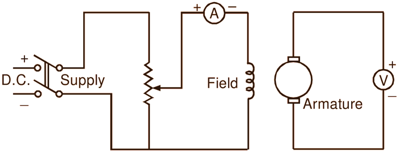
(a)
(b)
Fig. 1: Determination of open circuit characteristic of a dc generator
The field current is gradually increased from zero onwards till the armature voltage attains about 125
COMPARISON OF EXTERNAL CHARACTERISTICS OF DIFFERENT TYPES OF DC GENERATORS
For comparison, the external characteristics of different types of dc generators are drawn together in Fig. 2. While drawing these characteristics, the rated voltage is assumed to be same for all the generators.
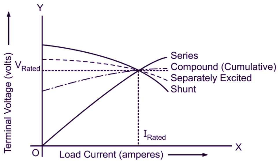
Fig. 2: External characteristics of different types of d.c. generators
VOLTAGE REGULATION
The voltage regulation of a dc generator (irrespective of the kind of excitation employed) is defined as the change in its terminal voltage when the load is reduced from rated value to zero, expressed as a percentage of the rated-load voltage. This change in voltage should be observed under the following conditions
- The test should be conducted at rated speed allowing for the change in speed inherent in the prime mover.
- After adjusting the rated-voltage at rated-load, the excitation should remain constant during the test for separately excited machines and external resistance in the field circuit shall remain constant for self-excited machine.