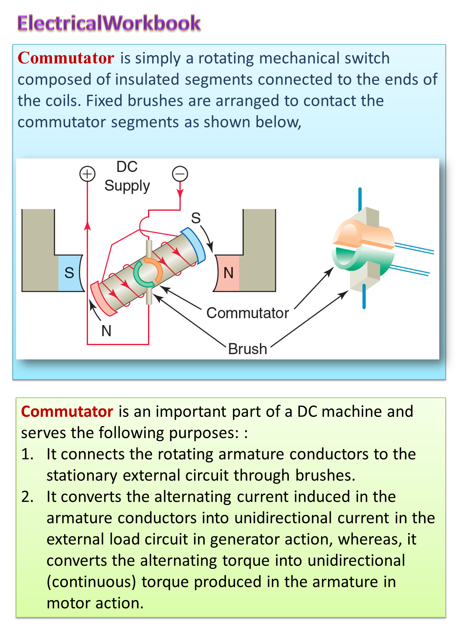
Construction of Commutator
The commutator is a split ring of larger size with large number of splits (commutator segments). It is called a mechanical rectifier in generator and an inverter in motor. The connections to the commutator depends upon the type of armature windings. These are made of hard copper so as to withstand the brush forces which are placed upon the commutator segments. The position of the brushes is generally based on the winding. Commutator consists of number of segments or bars insulated from each other and are combined together tightly to form a cylinder as shown in figure (1), and fitted on the insulated shaft of the armature. This is known as commutator.
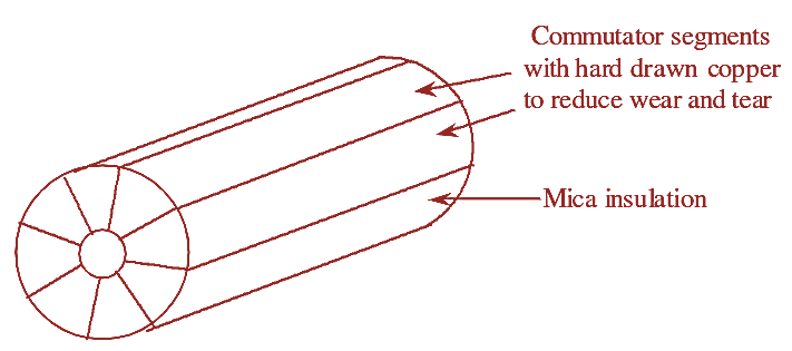
Figure (1): Commutator.
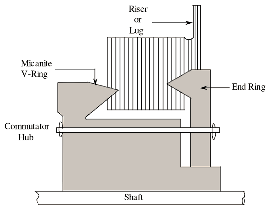
Figure (2): Sectional View of Commutator
To insulate the segments of commutator thin layers of (0.5 to 1 mm) mica is used. The ends of the coils wound on the armature are soldered on the segment of commutator. The insulating mica sheet is usually M or V shaped so as to prevent the segments from flying out due to centrifugal forces as shown in figure (2).
Working of Commutator
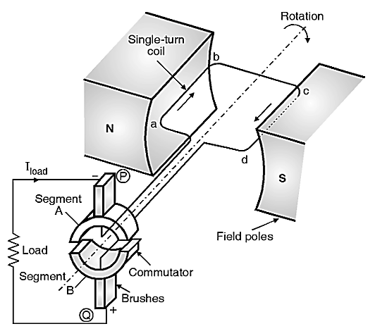
(a) DC generator with simplified commutator
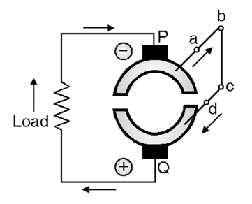
(b) Simplified construction
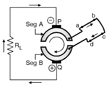
(c) Initial equivalent circuit
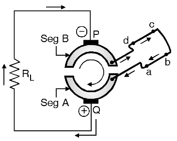
(d) Equivalent circuit after half rotation
Figure (3): Commutator Working.
We know that the emf induced into the rotating conductor is always sinusoidal. The commutator is used to convert it into a unidirectional (dc) emf. Thus “commutation” is the process of converting ac voltage into dc. It is similar to rectification.
The action of commutator is as follows, Refer Fig. 3(a) which shows a single turn dc generator, with the commutator in its simplest form. We assume that the commutator has been divided only into two segments namely segments A and B. The simplified construction is shown in Fig. 3(b). The commutator segments A and B are connected to the brushes P and Q respectively. Commutator segments, A and B are connected to conductors “ab” and “cd” respectively and rotate together.
According to Fleming’s light hand rule, the induced current in coil “ab” and “cd” as shown in Fig. 3(b). Hence brush P becomes negative and Q becomes positive as shown in Fig. 3(b). The current Iload through external load resistance RL flows from bottom to top as shown in Fig. 3(b).
After half the rotation, the segments A and B of the commutator will change their positions as shown in Fig. 3(d). So brush P is in contact with segment B and Q is in contact with segment A. The directions of currents induced in conductors “ab’ and “cd” are reversed as shown in Fig. 3(d). So brush P continues to be negative and brush Q continues to be positive. Hence the current through the external load continues to flow from bottom to top as shown in Fig. 3(c). Thus the load current and load voltage has become unidirectional. Also the commutator converts the alternating voltage produced by the single turn alternator into a DC voltage. Thus a commutator operates as a rectifier which converts the ac voltage to DC voltage.
Function of Commutator in a DC Machine
- As the voltage build up in the armature conductors is A.C voltage, to convert it into D.C voltage commutator is used in the external circuit in generator operation. whereas in D.C motor it produces unidirectional torque.
- It facilitates the collection of current from armature.
- It helps in connecting the armature with the external circuit.
- It converts alternating quantity into a direct quantity (i.e., voltage or current) and vice-versa.
- It keeps rotor or armature m.m.f stationary in space even though the armature is rotating.