In this topic, you study Current Transformer (CT) – Working, Types & Diagram.
Current Transformers are used to measure alternating current, which exceeds the safe value of the ammeter. The Fig. 1 shows a C. T. The primary winding of C.T. carries current to be measured. The current is stepped down ie., a C.T. is a “step up” transformer. The secondary winding is connected to an ordinary ammeter. Thus the C. T. steps down the current equal to the full scale deflection (f.s.d.) value or safe value of the ammeter. The primary of a C. T. is connected in series with the line, whose current is to be measured. The primary current therefore is independent of the load on the secondary.
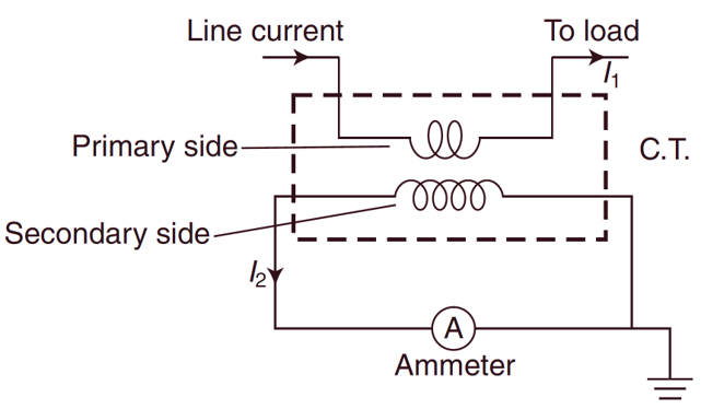
Fig. 1: Current Transformer
The primary winding of C. T consists of few turns of thick wire and hence there is no appreciable voltage across it. The secondary of the C. T. has large no. of turns of fine wire determined by the turn ratio. The ammeter (or wattmeter for power measurement) is connected directly across the secondary terminals, thus the secondary operates nearly under short circuit conditions. The current in the secondary is not governed by its load impedance rather it depends upon its primary current. The CT s. are rated in volt amperes (VA) and they are available between 15 to 30 VA.
Types of C.T.s.
From construction point of view, the C. Ts are of following types :
- Clamp on/clip on/ Tong tester
- Bar type
Clamp on / Clip on / Tong tester
This C. T. can be used with a single conductor (Fig. 2). The core of the C. T. can be split opened with the help of a “trigger switch” provided with the device. Thus the core can be clamped around the live conductor to measure the current. This arrangement avoids breaking the circuit for connecting C.T. The single live conductor act as a primary and the secondary is wound on the core of the C. T. The ammeter can be connected in the secondary. It is a portable instrument and generally used in laboratories.
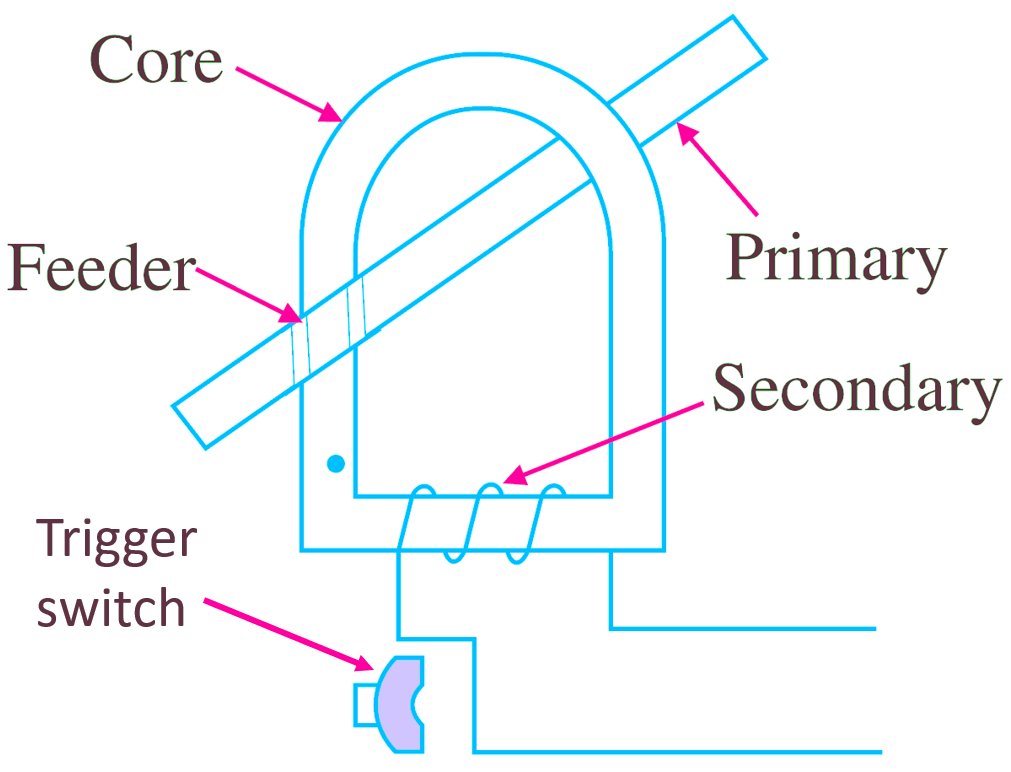
Fig. 1. Clamp on Meter.
Bar Type C. T.
It has a circular ring type core, on which secondary is Wound. It is used to measure current through a bus bar which is inserted through it. The ammeter is connected in the secondary. The instruments (ammeter etc.) placed on panel boards can be used (Fig. 3).
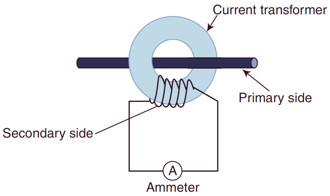
Fig. 3: Bar Type CT
Precautions in the use of C.T.
The C. T. should always be used with secondary short circuited through ammeter. wattmeter or relay etc. It should not be used with open secondary while primary carrying current. Here is the explanation:
- In normal operation short circuited secondary of a C. T. has demagnetising ampere turns and the flux density in the core is very low as compared in the primary. But if the secondary is open circuited, the demagnetising effect of secondary disappears and flux density in the core increases many times. This large flux induces a very high voltage in the secondary, it is so great that it may be fatal to the operator.
- In open circuit conditions, the C. T. may also be damaged, as Insulation break down may occur. Iron losses are increased to a great value and it may cause over heating of the core. The C. T.s. are usually provided with a “short circuiting switch” which should be closed before the secondary is opened for removal of the ammeter etc.
Applications of Current Transformer
- Current transformers are used with wattmeters. protective relays, magnetic circuit breakers, energy meters and power factor meters.
- It is used to extend the range of ammeters.
- It also extends the current coils of wattmeters and energy meters.
- It is commonly used for electric switch board meters.
- It is used for current control and sensing ground faults.
Important Points about Current Transformer
As the ratio of transformation (K) is equal to the voltage ratio (V2 / V1) and turn ratio (N2 / N1), But in case of CT the ratio (K) is not equal to the turn ratio. Moreover, its value depends upon magnetising and loss components of the excitation current. This causes various errors therefore, it needs proper construction of C.T., for this purpose the core of C. T. should have low reactance arid low core loss to keep the magnetising and loss components at low value. For this the material used for the core should have high permeability, low value of flux density, low hysteresis and low eddy losses. Now a days, the materials used for core are cold rolled grain oriented (C.R.G.O.) silicon steel, mumetal (75%), nickel 17% Fe), and permalloy (50% CO, 50% Ni). Two types of core construction are used for CT s. as
- Spiral
- Ring
Moreover, the core should have minimum number of joints.
Warning
The C. T. should never he operated with open circuited secondary.