The DIAC is an abbreviation for Diode AC semiconductor switch. The prefix ‘Di’ indicates, that the device has two terminals like diode. ‘AC’ means that the device controls the alternating current (a.c.) or can conduct current in either direction. In the thyristor family, the DIAC is used most commonly as a triggering device to trigger the TRIACs.
The Diac is a four laver bidirectional device with two terminals which can be switched from its OFF state to its ON state for either polarity of applied voltage. The switching can be achieved by simply exceeding the avalanche breakover voltage in either direction across its terminals. The DIACs are available with breakdown voltage ranging from 28 to 36 V and maximum pulse current 2 A.
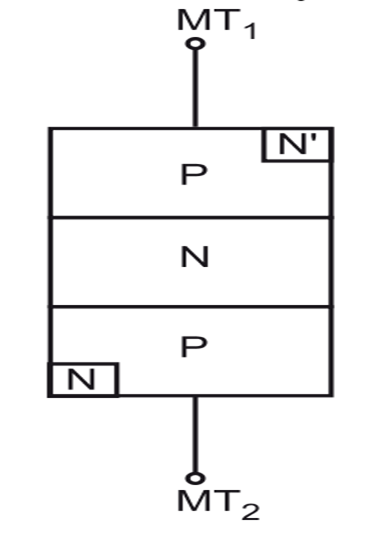
(a) Basic structure
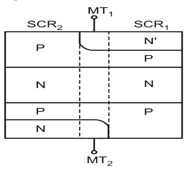
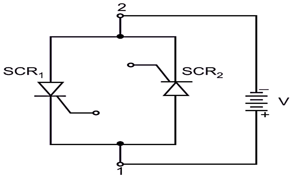
(b) Equivalent structure
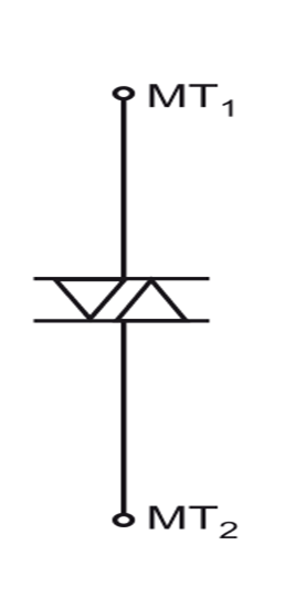
(c) Symbol
Fig. 1: Construction of a DIAC
Construction of DIAC
The basic structure of a DIAC is shown in Fig. 1(a). The construction of a DIAC is similar to a TRIAC but without a gate terminal drawn outside. It consists of four layers (i.e. PNPN) as shown in Fig. 1 (a). It may be noted that it consists of two four layer switches, i.e. two SCRs in anti-parallel. These two switches are PNPN and PNPN’ as shown in its equivalent circuit of Fig. 1(b). Since the DIAC conducts in both directions for either polarity of voltages the terms anode and cathode are not used for the DIAC. Hence the terminals are simply designated by numbers instead of anode and cathode such as terminal one MT1 and terminal two MT2. It may be noted that the DIAC consists of two SCRs connected in parallel but in opposite direction i.e. anti-parallel. Its schematic symbol is shown in Fig. 1(c).
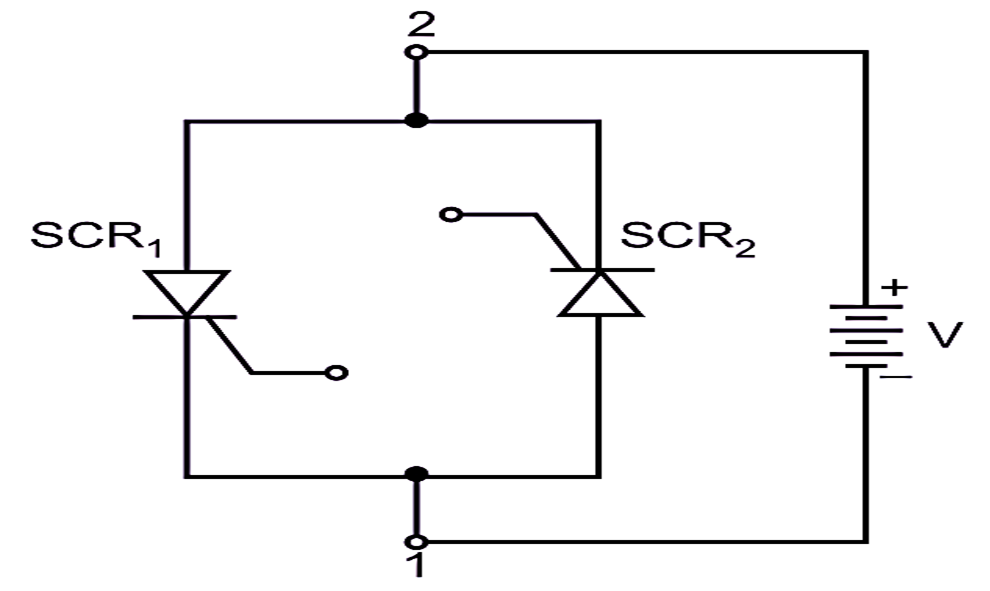
(a) Forward biasing of DIAC
(b) Reverse biasing
Fig. 2: Operation of a DIAC
Forward bias
Consider the equivalent structure of a DIAC as shown in Fig. 2 (a). The DIAC is said to be forward biased when the terminal two MT2 is positive with respect to the terminal one MT1.
The switch SCR1 (PNPN’) is forward biased and the switch SCR2 (PNPN) is reverse biased. Therefore, a small leakage current will flow through the DIAC due to SCR1 and SCR2 as they are not switched on. Both are initially off. As the applied voltage is increased, the leakage current will continue to flow until the forward voltage (V) reaches to the breakover voltage of SCR1. At this voltage, an avalanche breakdown of switch SCR1 occurs and the DIAC turns on with the sudden increase in current through it due to conduction of SCR1. The voltage across the device then falls back down to the break-back voltage (Vw) and the DIAC exhibits the negative resistance in forward biased condition of a DIAC.
Reverse bias
Consider the equivalent structure of a DIAC as shown in Fig. 2(b). The DIAC is said to be reverse biased when the terminal two MT2 is negative with respeci to the terminal one MT1. The switch SCR1 (PNPN’) is reverse biased and the switch SCR2 (PNPN) is forward biased. Therefore, a small leakage current will flow through the DIAC due to SCR1 and SCR2 as they are not switched ON. Both are initially OFF. As the applied voltage is increased, the leakage current will continue to flow until the reverse voltage V reaches the breakover voltage of SCR2. At this voltage, the avalanche breakdown of a switch SCR2 occurs and the DIAC turns on with the sudden increase in current through it, due to conduction of SCR2.
The voltage across the device then falls back to the break-back voltage Vw and the DIAC exhibits the negative resistance in the reverse condition of a DIAC. Thus the DIAC can be switched ON from its OFF state for either polarity of applied voltage.
V-I Characteristics of DIAC
It is the curve between the voltage applied across the two terminals MT1 and MT2 and the anode current flowing through the DIAC. The DIAC has two types of V-I characteristics, namely forward and reverse characteristics.
Forward characteristics:
The experimental set-up for plotting the forward characteristics of a DIAC is shown in Fig. 3 (a). Increase the applied positive voltage across the DIAC in small suitable steps. At each step, record the value of DIAC current and the voltage across it. Now, if we plot a graph with the terminal voltage Va along the horizontal (X) axis and the DIAC current (Ia) along the vertical (Y) axis, we obtain a curve marked ODEF as shown in Fig. 3 (b).
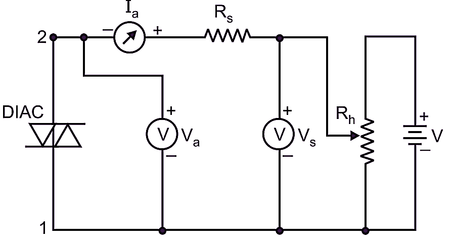
(a) Experimental set up
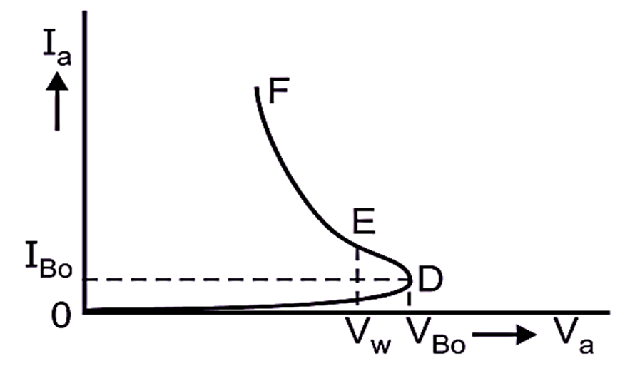
(b) Forward characteristic
Fig. 3 : Forward characteristics of a DIAC
Reverse characteristics:
The experimental set-up for plotting the reverse characteristics of a DIAC is shown in Fig. 4 (a). Increase the applied reverse voltage across the DIAC in small suitable steps.
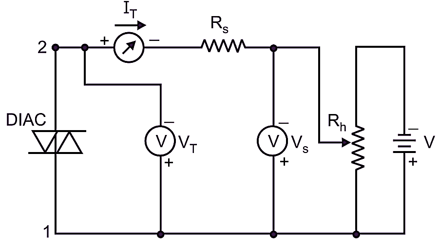
(a) Experimental set up
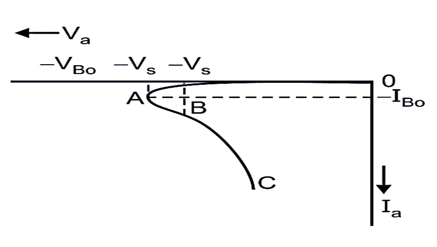
(b) Reverse characteristic
Fig. 4: Reverse characteristics of a DIAC
At each step, record the value of DIAC current and the voltage across it. Now, if we plot a graph with the terminal voltage Va along the horizontal (X) axis and the DIAC negative current Ia along the vertical (Y) axis, we obtain a curve marked OABC as shown in Fig. 4 (b).
Combined V-I characteristics of DIAC
The combined V-I characteristics of a DIAC in forward and reverse biased condition is as shown in Fig. 3. We can also apply a.c. voltage to the DIAC. The V-I characteristics of DIAC gives important information about the following points.
- The curves OABC and ODEF (Fig. 5) are symmetrical and identical. It is true because the operation of DIAC is identical in both directions of conduction.
- The DIAC does not conduct the current until the applied voltage of either polarity reaches the breakover voltage (± VBo).
- At the breakover voltage (typical value 30 V), the DIAC turns ON and the current through the DIAC increases rapidly as shown in Fig. 5.
- The operating voltages and currents are the same in either direction. Therefore, the DIAC is a symmetrical bilateral diode.
- The typical ON-state voltage drop of DIAC is 3 V.
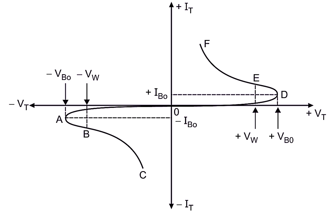
Fig. 5: Combined V-I characteristics of a DIAC
Applications of DIAC
The DIAC is used as a triggering device in TRIAC control systems such as
- for light dimming control.
- for heat control.
- for speed control of AC motors.