A silicon controlled switch is abbreviated as SCR. It is a unilateral four layer silicon device with four electrodes, namely anode, cathode, anode gate and cathode gate. It is a member of thyristor family. It is a unidirectional device.
Construction of Silicon Controlled Switch
Fig. 1 (a) shows the basic structure of a SCS.
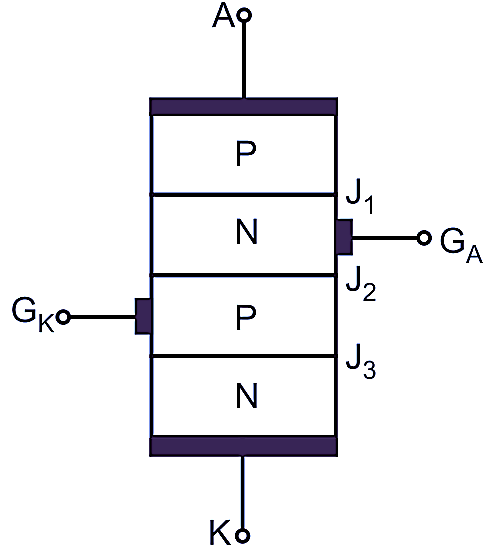
(a) Basic structure
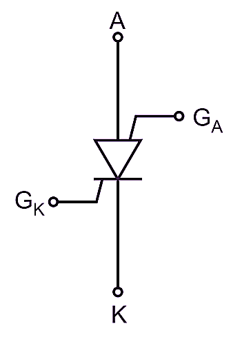
(b) Symbol
Fig. 1: Construction of SCS
It consists of four semiconductor layers PNPN. It has four terminals such as anode A, cathode K, anode gate GA and cathode gate GK. It has three junctions. Its construction is similar to that of a SCR. The SCS can also be manufactured using planer technique but in that case the anode is a ring of P-type diffused material surrounding all NPN transistor. The circuit symbol of a SCS is as shown in Fig. 1 (b). It is available at low power ratings.
Principle of Operation of Silicon Controlled Switch
The equivalent circuit with two transistor analogy of a SCS is as shown in Fig. 2.
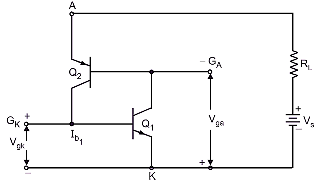
Fig. 2: Operation of SCS
The SCS is considered as consisting of a complementary pair of transistor with regenerative feedback. The operation of SCS is like a SCR about it can be turned ON by either a positive pulse at gage GK or a negative pulse of gate GA. Its construction is similar to that of a SCR.
The SCS is forward biased by applying a positive voltage at anode A with respect to cathode and no voltage is applied at the gates GK and GA. As the gate current is zero, both the transistors will be OFF. If a positive pulse is applied at the gate GK, the gate current will flow through the base of transistor Q1. Due to regenerative feedback action, the transistors, Q1 and Q2 are driven into saturation and heavy current will flow through the device from anode to cathode. This is forward ON (conduction) state of a SCS. The SBS can also be turned ON by applying a negative pulse at the anode gate GA. Thus the SCS can be turned ON by either a positive pulse at gate GK or a negative pulse at gate GA. The SCS can be turned OFF from its ON state by applying a positive pulse at anode GA or a negative pulse at cathode gate GK. Once the SCS is turned ON, it behaves like an SCR. The SCS can be turned OFF like SCR by reducing anode current below the holding current IH.
V-I Characteristics of Silicon Controlled Switch
The V-I characteristics of a SCS is shown in Fig. 3.
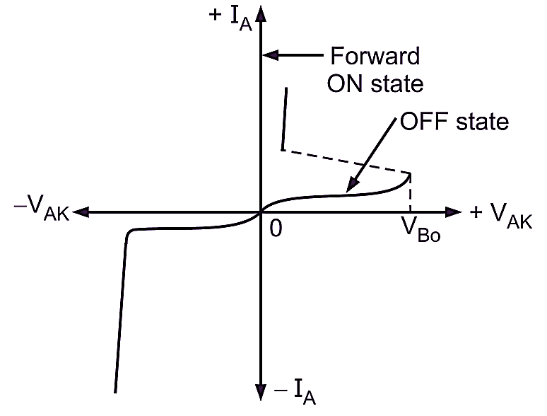
Fig. 3: V-I characteristic of SCS
Under forward biased condition, when a positive pulse voltage at the gate GK or a negative gate pulse voltage at the gate GA is below the breakover voltage, the SCS does not conduct the current. But the reverse saturation (leakage) current flows through the SCS. The SCS is now in forward blocking (OFF) state. Under forward biased condition, when a positive pulse voltage at the gate GK or a negative pulse voltage at the gate GA exceeds the breakover voltage, the SCS starts conducting current through it from anode to cathode. The anode current rises suddenly but the voltage across it drops to low voltage about 1 V. This is a forward conduction (ON) state of a SCS. The forward OFF and ON states are shown in Fig. 3.
Advantages of Silicon Controlled Switch
The advantages of SCS over SCR are as given below:
- It has fast turn-off.
- It can be turned-off with positive or negative pulse at either gate.
Applications of Silicon Controlled Switch
Some of the important applications of SCS are as given below:
- It is used mainly in low power sensing circuits.
- It is used in timers, registers and counters.
- It is used in digital logic circuits.
- It is used in pulse generators.
- It is used in oscillators.