In this topic, you study EMF Equation of a Transformer – Theory & Derivation.
When the primary winding (P) is connected to the ac supply, an alternating current flowing through it produces an alternating flux. This varying flux links with the secondary winding (S) through the core and produces an emf in it by mutual induction. But this flux produced by the primary winding while passing through the magnetic core, links not only the turns of the secondary winding but also the turns of the primary winding itself. Therefore, an emf is also induced in the primary winding due to self-induction. Now, let us derive the mathematical expressions for these emfs induced in the primary and secondary windings. For that, let
${{\text{N}}_{1}}$ = Number of turns on the primary winding
${{\text{N}}_{2}}$ = Number of turns on the secondary winding
${{\phi }_{\text{m}}}$ = Maximum value of the alternating flux linking both the windings, in webers
f = Frequency of supply, in hertz
Fig. 1 shows one cycle of sinusoidal flux established in the core by the sinusoidally varying alternating current in the primary winding. From this figure, it will be readily seen that the flux grows from zero to its maximum value in one quarter of the cycle i.e. in a time seconds.
∴ Average rate of change of flux
\[\text{= }\frac{{{\phi }_{\text{m}}}}{\text{t}}=\frac{{{\phi }_{\text{m}}}}{\left(1/4\text{f} \right)}=4{{\phi }_{\text{m}}}\text{f webers/second}\]
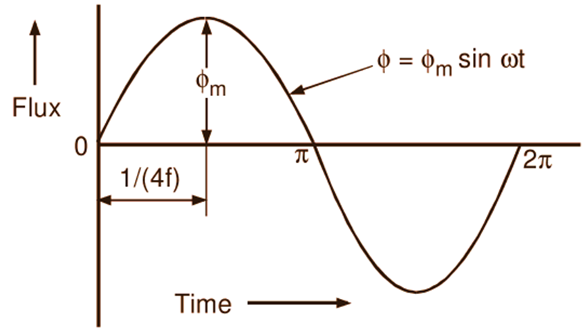
Fig. 1: A cycle of flux in the transformer core
Then, from Faraday’s law of electromagnetic induction, it follows that:
Average emf induced in each turn
\[\text{= Average rate of change of flux}\]
\[=4{{\phi }_{\text{m}}}\text{f volts }\left( \text{Numerically},\text{ } \text{e}=-\text{N}\frac{\text{d}{{\phi }_{\text{m}}}}{\text{dt}} \right)\]
Since the flux is assumed to vary sinusoidally with time, emf induced by it in each turn of both the windings will also be sinusoidal. Now, we know that for a sine wave,
\[\text{Form factor = }\frac{\text{R}\text{.M}\text{.S value}}{\text{Average value}}=1.11\]
∴ R.M.S. value of emf induced in each turn
\[\text{= }1.11\text{ }\left( \text{Average value} \right)\]
\[\text{= }1.11\text{ }\times 4{{\phi }_{\text{m}}}\text{f}\]
\[\text{= }4.44{{\phi }_{\text{m}}}\text{f volts}\]
∴ R.M.S. value of induced emf in the primary winding,
\[{{\text{E}}_{1}}=\left( \text{Induced emf/turn} \right)\times \text{Number of primary turns}\]
\[=4.44{{\phi }_{\text{m}}}\text{f}\times {{\text{N}}_{1}}\text{ volts}\]
Thus,
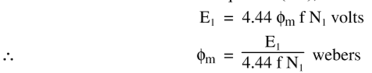
\[{{\text{E}}_{1}}=4.44\text{ }{{\phi }_{\text{m}}}\text{f }{{\text{N}}_{1}}\text{ volts}\]
Similarly, R.M.S. value of induced emf in the secondary winding is given by
\[{{\text{E}}_{2}}=4.44\text{ }{{\phi }_{\text{m}}}\text{f }{{\text{N}}_{2}}\text{ volts}\]
Example 1
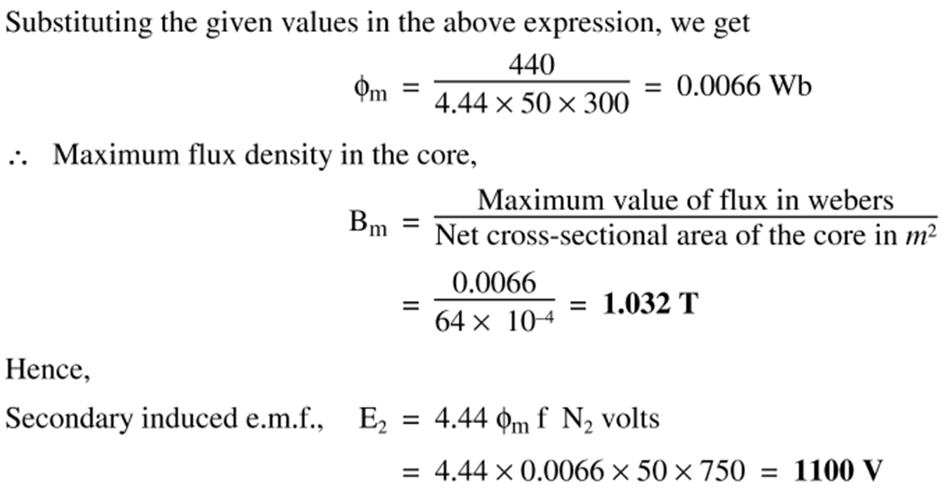
A single phase, 50 Hz transformer has 300 primary turns and 750 secondary turns. The net cross-sectional area of the core is 64 sq.cm. If the primary induced emf is 440 V, find
(a) Maximum flux density in the core,
(b) EMF induced in the secondary.
Solution : We know that,