In this topic, you study Instrument Transformers – Definition, Types & Diagram.
Measuring instruments in the heavy-current or high voltage a.c. circuits are always operated through special transformers known as instrument transformers. With these transformers, instruments designed for low-voltage circuits and having single standard current and voltage ranges can be used for all high voltage circuits, irrespective of the voltage and current ratings of the circuits. These transformers apart from extending the range of the instruments, isolate them from high voltage circuits and thus make their handling more safe. They are also useful for operating many types of protective equipments such as relays.
Types of Instrument Transformers
Current transformers (CTS) and potential transformers (PTS) are the two main types of instrument transformers.
Current Transformer
Large alternating currents which cannot be passed directly through the operating coils of the ammeters and current coils of the wattmeter, energy meters and power factor meters are reduced in some fixed proportion by means of these transformers.
(a)
(b)
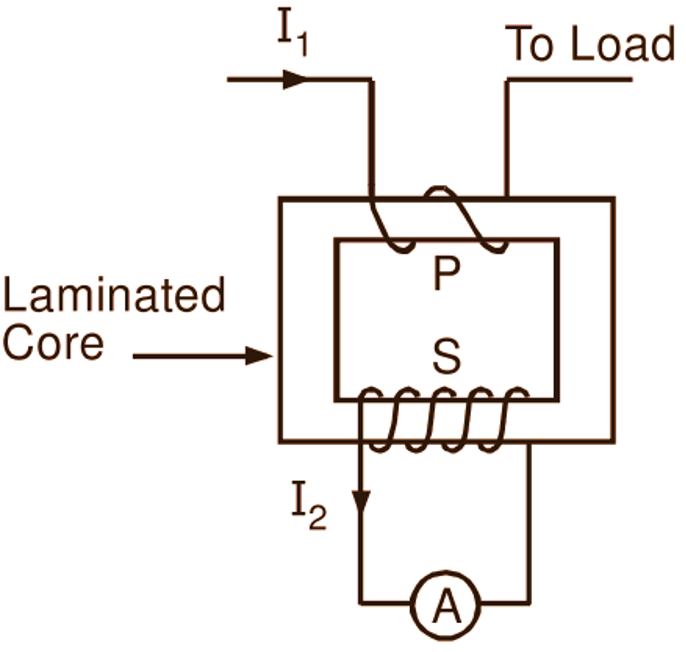
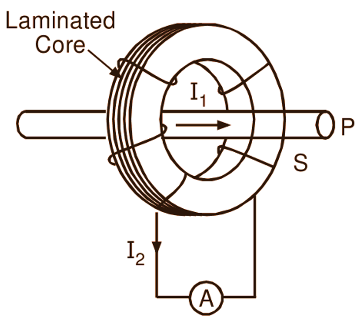
Fig. 1: Current transformer (a) With the wound primary and secondary, (b) With bar primary
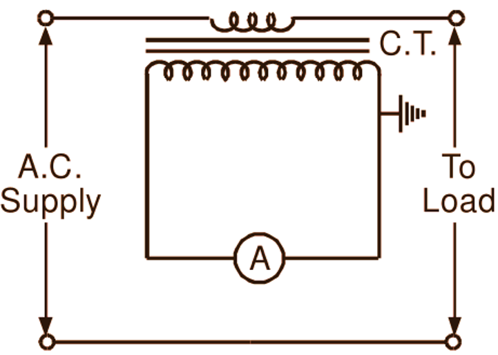
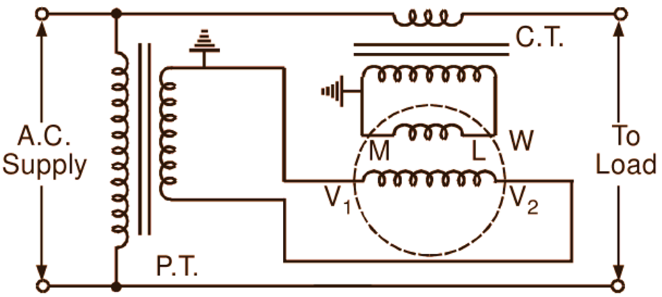
The primary winding (P) of a current transformer has only one or few turns of wire with thick cross-section and is connected in series with the line carrying the high currents (Fig. 1 (a)). In fact, when the current is large, the bus-bar itself often forms the primary (P) of a current transformer (Fig. 1 (b)). On the other hand, its secondary winding (S) has a large number of turns of fine wire and is usually rated for 5 A irrespective of the primary current rating. The ammeter or current coil of any of the instruments such as a wattmeter, an energy meter, a power factor meter, etc. is connected to the terminals of the secondary winding. As an illustration, Fig. 2 (a) and Fig. 2 (c) respectively show the connections of an ammeter and current coil of a wattmeter to the line through a current transformer.
(a)
(b)
(c)
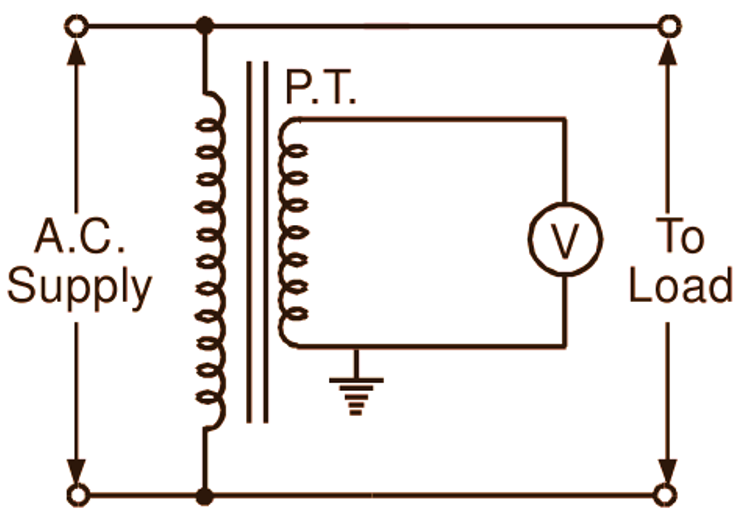
Fig. 2: Typical connections of the instrument transformers and the instruments for single phase measurements
Many times, it becomes essential to measure the current in a heavy-current busbar without breaking the current circuit. Under such conditions, a clip-on type current transformer (Fig. 3) with a suitably split and hinged core, upon which the secondary winding is wound, can be employed. The split core of this transformer is simply fitted round the busbar, which acts as the primary winding of the transformer.
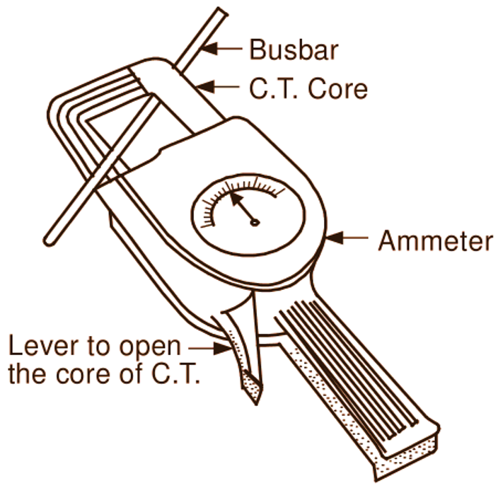
Fig. 3: Clip-on meter
In general, if N1 and N2 are the turns in the primary and secondary windings, and I1 and I2 are the currents in these windings, then neglecting the power loss in itself, a current transformer similar to ordinary power transformer has the following simple relationship :
\[\frac{{{\text{I}}_{\text{1}}}}{{{\text{I}}_{\text{2}}}}=\frac{{{\text{N}}_{\text{2}}}}{{{\text{N}}_{\text{1}}}}\]
One important precaution that should be taken while using a current transformer is that its secondary should never be opened when current is flowing in its primary circuit. This is because, in a current transformer, the primary current is determined entirely by the load on the system and not by the load on its own secondary. Hence, the primary m.m.f. is not reduced when the secondary circuit is opened. This is obviously contradictory to the behavior of a power transformer. Therefore, under such conditions, in the absence of counter m.m.f. due to secondary current, a very high flux density is produced in the core. This high flux density and a large ratio of secondary to primary turns cause very high induced voltage in the secondary winding which produces severe strain on the insulation and endanger the safety of the operator. The increased core loss causes overheating of the transformer. The core of the transformer is permanently magnetized and consequently the accuracy of the current transformer is lost.
Potential Transformer
High alternating voltages are reduced in fixed proportion for measurement purposes with the help of these transformers. The construction of the potential transformers is similar to that of ordinary two winding transformers except that they have very small power rating and high voltage ratio. Obviously, the primary winding of a potential transformer which is connected across the lines has a large number of turns. On the other hand, its secondary winding has a much smaller number of turns and is usually rated for 110 V irrespective of the primary voltage rating. The voltmeter or a potential coil of any of the instruments such as a wattmeter, an energy meter, power factor meter, etc. is connected across the secondary winding. As an illustration, Fig. 2 (b) and Fig. 2 (c) respectively show the methods of connecting a voltmeter and a potential coil of a wattmeter to the lines through a potential transformer. It should be noted that one end of a secondary of both the instrument transformers (current and potential) is always grounded as a safety measure. If the power loss in the potential transformer itself is neglected, it has the following simple relationship:
\[\frac{{{\text{V}}_{\text{1}}}}{{{\text{V}}_{\text{2}}}}=\frac{{{\text{N}}_{\text{1}}}}{{{\text{N}}_{\text{2}}}}\]
where V1 and V2 are the voltages on the primary and secondary sides. Thus, as in the ordinary power transformer, the voltage per turn is the same on the primary and secondary sides. The meters used in conjunction with the instrument transformers in the manner described above can be calibrated to give directly the electrical quantities (such as current, voltage, power, energy, etc.) to be measured taking into account the ratios of the transformers.
Rating of Instrument Transformers
Rating or rated burden of the instrument transformer is the load in volt-amperes which the transformer is designed to supply to the indicating instrument or meter, at its rated secondary current or voltage.
Errors in the Instrument Transformers
For precise measurement, transformers must be designed for accurate voltage or current ratio and minimum displacement (or phase shift) between input voltages and currents and the corresponding output quantities. The performance of the instrument transformers under different operating conditions is affected by two types of errors, namely (i) ratio error and, (ii) phase angle error.
Ratio Error
In actual practice, current ratio I1 / I2 of the current transformer differs from the ratio of number of secondary turns to primary turns N2 / N1 by an amount which depends upon the magnitude of the exciting current of the transformer, and upon the current and power factor of the secondary circuit. Similarly, voltage ratio V1 / V2 of the potential transformer also differs from its turns ratio N1 / N2. The current or voltage ratio of the transformer is, therefore, not constant under all conditions of the load and of frequency. This fact leads to the ratio error in the instrument transformer. The ratio error in the instrument transformer may be defined as follows:
Where,
\[\text{Ratio error = }\frac{\text{Nominal ratio}-\text{Actual ratio}}{\text{ Actual ratio}}\]
\[\text{Nominal ratio}=\frac{\text{Rated primary current}}{\text{Rated secondary current}}\]
…..for the current transformer
\[\text{Nominal ratio}=\frac{\text{Rated primary voltage}}{\text{Rated secondary voltage}}\]
….for the potential transformer
\[\text{Actual ratio}=\frac{\text{Actual primary current}}{\text{Corresponding secondary current}}\]
…..for the current transformer
\[\text{Actual ratio}=\frac{\text{Actual primary voltage}}{\text{Corresponding secondary voltage}}\]
….for the potential transformer
Ratio error in the instrument transformer is responsible for introducing error in its current or voltage measurement. As mentioned earlier, this error is dependent upon the value of the exciting current (mainly upon its core-loss component, Ic) of the transformer, and upon the secondary current and power factor.
Phase Angle Error
For accuracy in the power measurements, it is necessary that the phase angle between the primary and secondary currents or primary and secondary voltages should be exactly 180o. In practice, this condition is not exactly fulfilled. The angle, say β by which this phase angle departs from 180o is known as the phase angle or phase angle error of the transformer. The phase angle error has no effect when the transformer is used for measuring only current or voltage, but it does introduce error into the power and energy measurements. Similar to the ratio error, this error is also dependent upon the value of the exciting current (mainly upon its magnetizing component, Im) of the transformer, and upon the secondary current and power factor.
Classification of Instrument Transformers
Based on accuracy, instrument transformers are divided into different classes, namely AL, BL, A, B, C and D. These classes are in order of decreasing accuracy, class AL being suitable for testing work of the highest precision.
Advantages of Instrument Transformers
- With instrument transformers, instruments designed for low-voltage circuits and having single standard current and/or voltage ranges can be used for all high voltage circuits, irrespective of the voltage and current ratings of the circuits. (ii) These transformers, apart from extending the range of the instruments, isolate them from high voltage circuits and thus make their handling more safe.
- Several instruments can be economically fed by one transformer.
- Instrument transformers are also useful for operating many types of protective equipments such as relays.
Disadvantages of Instrument Transformers
Instrument transformers cannot be used on dc.